


22
ENG
“EVD ice” +0300038EN - rel. 1.1 - 23.04.2018
Parameter
Description
Def.
Min
Max
Type Carel Modbus® R/W Note
Pctrl_rev_set
Reserved
-
-20(-290)
200(2900)
A
23
22
R/W
SH_actual_set
Reserved
0
-40(-72)
180(324)
A
24
23
R
SH_Set_smooth_line
Superheat Setpoint-Offset for smooth line
0
-55(-99)
55(99)
A
25
24
R/W
S1_value_remote
Reserved
0
-20(-290)
200(2900)
A
26
25
R/W
Tab. 8.b
8.9 Control states
The electronic valve controller can have six different control states,
each of which may correspond to a specific phase in the operation of
the refrigeration unit and a certain status of the driver-valve system. The
states are as follows:
•
forced closing: initialisation of the valve position when switching the
instrument on;
•
standby: no temperature control, unit OFF (at temp.);
•
wait: opening of the valve before starting control, also called pre-
positioning, when powering the unit on;
•
control: effective control of the electronic valve, unit ON;
•
positioning: step-change in the valve position, corresponding to the
start of control when the cooling capacity of the controlled unit varies
(only EVD connected to a pCO);
•
stop: of control with closing of the valve, corresponds to the end of
temperature control of the refrigeration unit, unit OFF (at temp.).
Forced closing
Forced closing is performed after the driver is powered on and corresponds
to the typical number of closing steps for CAREL E2V and E3V unipolar valves.
This is used to realign the valve to the physical position corresponding to
completely closed. The driver and the valve are then ready for control and
both aligned at 0 (zero). At power-on, first a forced closing is performed,
and then the standby phase starts. The valve is also closed in the event of
a mains power failure if the Ultracap module is connected. In this case, the
“Forced valve closing not completed” parameter is set to 1. On restarting, if
the valve forced closing procedure is not completed successfully:
1.
the Master programmable controller (pCO) will check the value of the
parameter, and if equal to 1 will decide the best strategy to adopt,
based on the application;
2.
on restarting the driver positions the valve as explained in the paragraph
“Pre-positioning/start control”. The parameter is set to 0 (zero) by the
Master controller (e.g. pCO), or alternatively by pressing the PRG/
Set button on the keypad. Once the parameter has been set to 1,
the driver sets it back to 0 (zero) only if an emergency forced closing
procedure is completed successfully.
Note:
lthe user can only select the resolution of the valve control
signal: 480 or 960 steps.
Par. Description
Def. Min. Max. UoM
U3 Valve control steps: 1 / 2 = 480/ 960 steps
1
1
2
-
Standby
Standby corresponds to a situation of rest in which no signals are received
to control the electronic valve: it is closed and manual positioning can be
activated. This status is normally set on the driver when the refrigeration
unit is shutdown manually (e.g. from the supervisor) or when reaching the
control set point. It can also occur when opening the digital input (which
involves closing the valve) or in the event of a probe alarm. In general, it can
be said that the electronic valve driver is in standby when the compressor
stops or the control solenoid valve closes.
Pre-positioning/start control
If during standby a control request is received, before starting control the
valve is moved to a precise initial position. Internally, the pre-positioning time
is set at 6 s and represents the time that the valve is held in a fixed position.
By default the valve is opened 50 % when starting (from digital input), so as to
minimise the movement needed to reach the correct position.
Par. Description
Def.
Min.
Max. UoM
U4 Valve opening at start-up
50
0
100
%
This parameter should be set based on the ratio between the rated
cooling capacity of the evaporator and the valve (e.g. rated evaporator
cooling capacity: 3kW, rated valve cooling capacity: 10kW, valve opening
= 3/10 = 33%).
The driver calculates the valve opening based on the required capacity:
If required capacity is 100%:
Opening (%)= (Valve opening at start-up);
If required capacity is less than 100% (capacity control):
Opening (%)= (Valve opening at start-up) x (Current unit cooling
capacity), where the current unit cooling capacity is sent to the driver
via RS485 by the pCO controller. If the driver is stand-alone, this is always
equal to 100%.
Notes:
•
this procedure is used to anticipate the movement and bring the valve
significantly closer to the operating position in the phases immediately
after the unit is powered on;
•
if there are problems with liquid return after the refrigeration unit starts
or in units that frequently switch on-off, the valve opening at start-up
must be decreased. If there are problems with low pressure after the
refrigeration unit starts, the valve opening must be increased.
Wait
When the calculated position has been reached, regardless of the time taken
(this varies according to the type of valve and the objective position), there
is a constant 5 second delay before the actual control phase starts. This is to
create a reasonable interval between standby, in which the variables have no
meaning, as there is no flow of refrigerant, and the effective control phase.
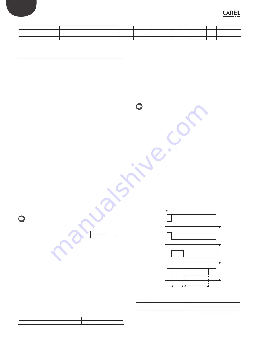
Control
The control request can be received by the closing of the digital input
or via network (RS485). The solenoid or the compressor are activated
when the valve, following the pre-positioning procedure, has reached
the calculated position. The following figure represents the sequence of
events for starting control of the refrigeration unit.
t
t
t
t
OFF
ON
R
OFF
ON
P
OFF
ON
S
OFF
ON
A
T1
W
Fig. 8.o
Key:
A
Control request
T1 Pre-positioning time
P
Pre-positioning
W Wait (wait)
S
Standby
t
Time
R
Control
Positioning (change cooling capacity)
This control status is only valid for controllers connected to the pCO
via RS485. If there is a change in unit cooling capacity of at least 10%,
sent from the pCO via RS485, the valve is positioned proportionally. In
practice, this involves repositioning starting from the current position in