4
Part Number 3E1086 R2
September 2002
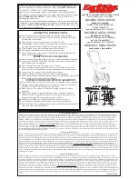
Mounting
Note: The Prox Plus 125 reader has been designed to metric specifications therefore
any imperial measurements provided are approximate only.
The Prox Plus 125 reader is designed to be mounted on any solid flat surface including
metal surfaces.
The recommended mounting height for the Prox Plus 125 reader is 1100mm from floor
level to the centre of the reader unit. However this may vary in some countries and you
should check local regulations for variations to this height.
Note: The grommet through which the cables feed into the base of the Prox Plus 125
reader helps to keep the unit waterproof.
Drill a 20mm (
3
/
4
inch) diameter hole for the base extrusion through or into the mounting
surface to a minimum depth of 40mm (1
1
/
2
inch).
Run the building cabling through the base and grommet.
Fit the base to the 20mm (
3
/
4
inch) hole and secure it to the mounting surface using the
four fixing screws.
Fit the screw caps over each fixing screw. The screw caps prevent water from entering the
reader via the fixing holes. The caps must be installed for the Prox Plus 125 reader to
comply with the environmental specification.
Note: It is very important that the base of the reader is flush with and tight against
the mounting surface. If you are mounting the Prox Plus 125 reader on a
rough surface you should make the surface as smooth as possible under the
reader and up to 25mm (1 inch) around the reader.