background image

S T E P  9

S T E P   9   –   C o n t r o l l e r

70

docs.carbide3d.com

[email protected]

71

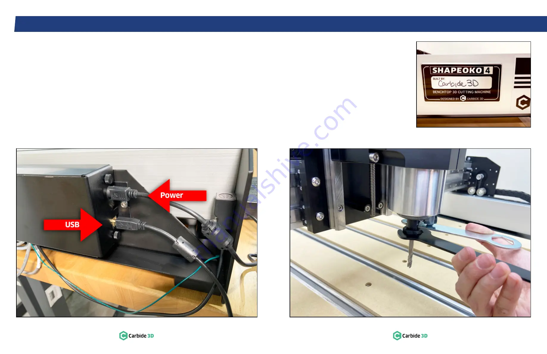
9.8   Connect Power and USB

1.  Plug the power cable into the power port at 

the back of the controller. 

See 

Fig. 9-9

.

a.  Flat side of the connector faces out.

2.  Plug the USB cable into the USB port below 

the power port. 

Figure 9-9

Figure 9-10

Figure 9-11

9.9   Install an End Mill

These instructions are specific to the Carbide 

Compact Router. For all other routers, refer to the 

router manual for operating, safety, and end mill 

installation information. 
The Carbide Compact Router includes a 0.25″ 

collet and nut, 22mm collet nut wrench, and 13mm 

spindle wrench.

1.  Replace the stock collet with the included 

0.25″ precision collet.

2.  Insert the end mill shank into the loosened 

collet a minimum of 0.75

 (20mm), the entire 

length of the collet and nut. 

3.  Use the 22mm and 13mm wrenches to tighten 

the collet nut securely. 

See 

Fig. 9-10

.

WARNING: 

Never tighten the collet nut without an 

end mill inserted in the collet.

Congratulations, the assembly is complete! 

All that’s left to do is sign and proudly display your 

Shapeoko 4 build plate. 

See 

Fig. 9-11

.

IMPORTANT: 

Before homing your machine, 

go 

to the next page to update the configuration 

settings

 . 

Summary of Contents for Shapeoko 4 XXL

Page 1: ...Shapeoko 4 XXL ASSEMBLY GUIDE...

Page 2: ...ers and Drag Chain Support Panels 6 1 3 Assemble Baseframe 7 1 4 Install Cable Tie Mounts 7 STEP 2 Y RAILS 8 2 1 Review Box 2 Components 9 2 2 Install Y Left Rail 10 2 3 Install Y Right Rail 11 STEP 3...

Page 3: ...o avoid contaminating them is recommended Inspect end mills carefully before each use and ensure that they are securely held by the collet Debris Disposal Recycle or safely dispose of milling debris a...

Page 4: ...mm Button Head Cap Screw 8 I Cable Tie Mount 4 J M3 6mm Button Head Cap Screw 4 K Pack of 100 Cable Ties SET ASIDE FOR USE IN STEP 9 1 L Extra Hardware Bag3 Not Individually Pictured 1 J M3 6mm Button...

Page 5: ...igs 1 2 and 1 3 a Snug the screws then back out turn b Don t worry about squaring the baseframe yet Figure 1 3 1 4 Install Cable Tie Mounts 1 Use a 2mm hex key and four 4 M3 6mm BHCS to secure two 2 c...

Page 6: ...s Item Description Qty U Y Axis LEFT Extrusion Rail with Shapeoko 4 Decal Y Left Rail 1 V Y Axis RIGHT Extrusion Rail with Carbide 3D Decal Y Right Rail 1 W Y Axis Side Skirt SET ASIDE FOR USE IN STEP...

Page 7: ...rail to outside 2 Use a 5mm hex key and four 4 M6 85mm shoulder bolts to loosely attach the Y Right rail to the standoffs See Fig 2 2 Figure 2 3 a Insert bolts in order front back center b Ensure bolt...

Page 8: ...E Inspect the Y Axis carriage plates at either end of the gantry for shipping damage Item Description Qty Y X Axis Gantry Assembly with Pre Installed X Axis Proximity Switch 1 Z X Axis Drag Chain Supp...

Page 9: ...at its greatest and the V wheels are OPEN When the dimple is facing DOWN they are CLOSED Figs 3 2 and 3 3 When adding tension to a loose V wheel turn the eccentric nut CLOCKWISE Turning counter clockw...

Page 10: ...ion Figure 3 5 Figure 3 6 2 Pick the gantry up and rest the X rail on its back across the Y rails See Fig 3 4 a Top of X rail pointing to the back of the machine b Top back V wheels resting on the lef...

Page 11: ...eft Endplate 1 CC Back Right Endplate with Pre Installed Y Axis Proximity Switch 1 DD Front Left Endplate 1 EE Front Right Endplate with Integrated Power Button 1 FF 4 Pin Male to Female Power Extensi...

Page 12: ...ll only connect one way Do not force a connection See Fig 4 3 Figure 4 2 Figure 4 3 2 Align the front right endplate with the four M6 screw holes in the front end of the Y Right rail a Power button fa...

Page 13: ...een the endplate and drag chain support panel or the end of the rail Figure 4 4 4 4 Install Y Left Endplates 1 Position the two remaining endplates at either end of the Y Left rail See Fig 4 5 a Curve...

Page 14: ...simultaneously touch the front endplates See Fig 4 6 3 Use a 5mm hex key and fully tighten the front left and front right shoulder bolts securing the Y rails to the baseframe a Fully tighten the rema...

Page 15: ...cket Head Cap Screw 2 Y Axis Belt Kit 2 II 15mm 2GT 1400mm Belt 2 JJ 15mm Belt Clip Pair Front and Back 2 N M5 12mm Socket Head Cap Screw 4 J M3 6mm Button Head Cap Screw 2 KK X Z Carrier Plate 1 LL M...

Page 16: ...l and the X Z carrier plate 5 4 Install X Z Carrier Plate 1 Place the X Z carrier plate onto the gantry aligning the two pre installed V wheels on the top with the upper V rail 2 Use the 3mm hex key t...

Page 17: ...and extend the belt away from the integrated nut 5 6 Install X Motor and Belt 1 Locate the X Axis belt kit a Contains two identical universal belt clips 2 Thread one end of the belt through a belt cl...

Page 18: ...or housing Fully tighten See Fig 5 7 8 Pull the slack out of the belt a Look through the slot in the top of the X motor housing to make sure the belt stays properly on the motor pulley 9 Thread the se...

Page 19: ...les in the upper right corner from the rear b Flange down 2 Use a 3mm hex key and two 2 M5 6mm BHCS to secure the bracket to the X Z assembly Fully tighten 5 8 Install Router Drag Chain Head Bracket 1...

Page 20: ...Identify the back side of the X Axis drag chain support panel See Fig 5 13 a The set of two M3 integrated nuts spaced about 1 apart and located at each end of the panel are pressed into the BACK SIDE...

Page 21: ...he belt into the Y Left front belt clip the slotted tab will be facing to the INSIDE of the machine 2 Place the belt clip on the Y Left rail at the front left endplate See Fig 5 15 a Small slotted tab...

Page 22: ...LY secure the belt clip to the M3 hole in the top of the rail 14 Use a 4mm hex key and one 1 M5 12mm SHCS to secure the clip to the back left endplate Fully tighten See Fig 5 17 15 Use a 2 5mm hex key...

Page 23: ...Drag Chain 4 pin male to female extension 2 3 pin male to female extension 1 1 TT Y Axis Data Drag Chain 4 pin male to female extension 4 3 pin female to 8 pin male proximity switch extension X and Z...

Page 24: ...attaches to the head bracket Figure 6 3 6 3 Secure X Axis Drag Chain Head and Tail 1 Use a 2mm hex key and two 2 M3 6mm BHCS to secure the X Axis drag chain to the data drag chain head bracket Fully t...

Page 25: ...rag chain support panel See Fig 6 5 2 Use a 2mm hex key and two 2 M3 6mm BHCS to secure the tail of the Y Axis drag chain to the support panel Fully tighten Figure 6 5 6 4 Attach Transition Bracket to...

Page 26: ...utton Head Cap Screw 8 T Self Adhesive Cable Tie Down 1 ZZ 65mm Router Mount 1 AAA M6 40mm Socket Head Cap Screw 2 BBB M5 40mm Socket Head Cap Screw 2 CCC M6 25mm Socket Head Cap Screw 2 DDD M6 10mm G...

Page 27: ...the router as far as it will go into the mount with the power cable extending left 2 If the router doesn t quite fit use a 3mm hex key and the M6 grub screw to gently pry open the mount See Fig 7 4 a...

Page 28: ...nt of the machine Figure 7 6 7 5 Insert Power Cable 1 Insert the router power cable through both drag chains and close up the links See Fig 7 7 2 Snap the tail links back onto both drag chains See Fig...

Page 29: ...is closest to the router b Flat side of the head of the drag chain attaches to the two integrated nuts in the bracket arm c Router cable must enter the chain OVER the bracket arm and through the openi...

Page 30: ...he Y Axis drag chain over the two M3 integrated nuts on the Y Left drag chain support panel See Fig 7 11 2 Use a 2mm hex key and the two 2 remaining M3 6mm BHCS to secure the tail to the support panel...

Page 31: ...ts NOTE The step 8 hybrid table box is not included if you selected No Table when you ordered your Shapeoko 4 If you did not order a hybrid table skip ahead to step 9 on page 62 Item Description Qty G...

Page 32: ...on to the baseframe a Insert screws in order front back center b Loosely insert all screws in an extrusion before fully tightening Figure 8 2 Figure 8 3 8 3 Install MDF Strips 1 Position the ten 10 MD...

Page 33: ...ide Controller 4 P M6 12mm Button Head Cap Screw 2 H M6 6mm Button Head Cap Screw 2 KKK USB Cable 1 LLL Shapeoko 4 Build Plate 1 MMM 201 0 25 Square End Mill 1 NNN Permanent Marker 1 OOO Power Supply...

Page 34: ...mm hex key and the M6 6mm BHCS to secure the back end of the controller mount and the grounding wire to the support panel Fully tighten See Fig 9 3 Figure 9 2 Figure 9 3 9 2 Install Controller Mount 1...

Page 35: ...e proximity switch cables into the 8 pin female connectors down the center of the controller labeled Z Y X See Fig 9 4 4 Plug the four 4 pin male stepper motor cables into the 4 pin female connectors...

Page 36: ...re 9 7 Figure 9 8 3 Extend the Y Left stepper motor extension cable across the back of the gantry to the Y Right carriage 4 Connect of the Y Left motor extension cable to the corresponding cable at Y...

Page 37: ...installation information The Carbide Compact Router includes a 0 25 collet and nut 22mm collet nut wrench and 13mm spindle wrench 1 Replace the stock collet with the included 0 25 precision collet 2...

Page 38: ...ration settings first 10 3 Update Machine Settings To update the machine s configuration settings see Fig 10 2 1 Click Settings in the top menu bar 2 Click the Send Configuration Button See Fig 10 2 3...

Page 39: ...achine 6 Once machine is in position click Done 7 On the Jog screen use the Y Y and X X buttons or the arrows on your keyboard to jog the gantry so the router is directly above the BitSetter trigger b...

Page 40: ...arbide3d com Find discussions on software issues Carbide Create Carbide Motion MeshCAM Carbide Copper Fusion 360 tutorial troubleshooting general machining questions product announcements community co...

Page 41: ...ur design where all of the toolpaths will be based from the X Y and Z coordinates Job zero is commonly set in the lower left corner of your stock Jog Move the router to a specific position a set of X...

Page 42: ...FETY CHECK CONDITION F Work Area Clear F PPE F Collet Cutter F V wheels Eccentrics F Router Spindle F End Mill Secure F Dust Extraction F Rails Belts F Wiring Switches F BitZero V2 Removed F Emergency...

Page 43: ...Carbide 3D 3630 Skypark Drive Torrance CA 90505 310 504 3637 support carbide3d com facebook com carbide3d instagram com carbide3d...

Reviews: