S T E P 7
S T E P 7 – R o u t e r
52
docs.carbide3d.com
53
7.4 Prepare Drag Chains
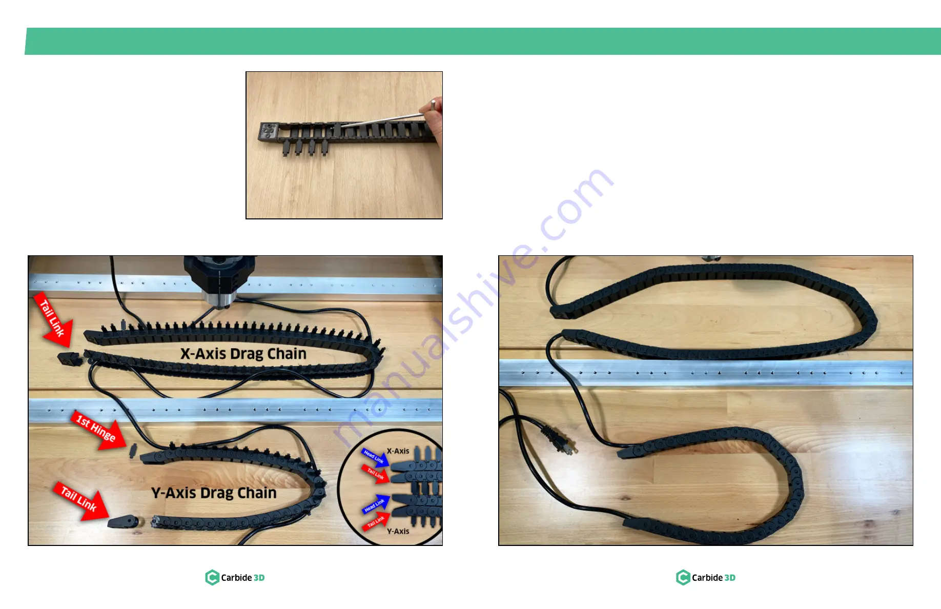
1. Open both drag chains.
a. Lay chains flat, hinged-side up, and use a
hex key to pry open the links from one side.
See
Fig. 7-5
.
2. Lay out the longer X-Axis drag chain as shown
in
Figs. 7-6
and
7-6 inset
.
a. Bottom (flat side) of both the head and tail
links face the front of the machine.
Figure 7-6
7.5 Insert Power Cable
1. Insert the router power cable through both
drag chains and close up the links.
See
Fig. 7-7
.
2. Snap the tail links back onto both drag chains.
See
Fig. 7-7
.
NOTE:
The power cable enters the head of the
Y-Axis drag chain BEHIND the head link.
Figure 7-7
Figure 7-5
3. Lay out the shorter Y-Axis drag chain as shown
in
Figs. 7-6
and
7-6 inset
.
a. Head and tail links are interchangeable.
4. Use a small screwdriver to pry the tail links off
both drag chains.
5. Remove the first link hinge at the head of the
Y-Axis drag chain.


