S T E P 4
S T E P 4 – E n d p l a t e s
24
docs.carbide3d.com
25
4.6 Install Side Skirts
1. Locate the two identical side skirts and
hardware set aside from the step 2 box.
2. Position one side skirt along the bottom-inside
edge of the Y-Right rail.
See
Fig. 4-7
.
a. Through-hole to the bottom.
3. Use a 3mm hex key and two (2) M5×8mm
BHCS to secure the skirt to the flanges of the
front and back endplates below the Y-Right
rail. Fully tighten.
Figure 4-7
4.5 Square Machine
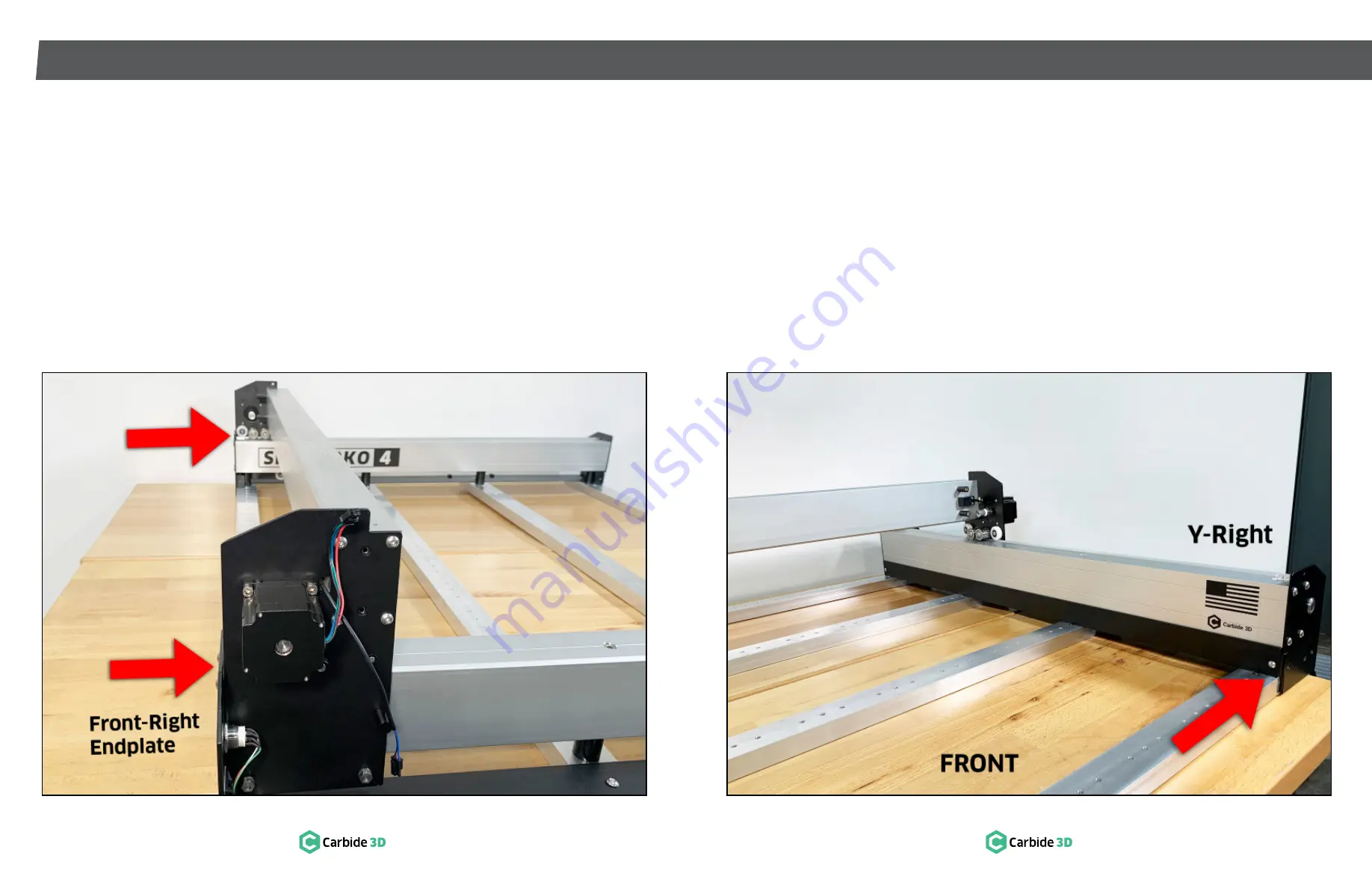
1. Slide the gantry as far forward as it will go.
2. Adjust the squareness of the baseframe until
both ends of the gantry simultaneously touch
the front endplates.
See
Fig. 4-6
.
3. Use a 5mm hex key and fully tighten the front-
left and front-right shoulder bolts securing the
Y-rails to the baseframe.
a. Fully tighten the remaining shoulder bolts,
moving front to back, sliding the gantry as
you go, and alternating sides.
Figure 4-6
4. Slide the gantry as far back as it will go. Both
ends of the gantry should simultaneously
touch the rear endplates.
5. Use a 4mm hex key to fully tighten the eight
(8) M6×6mm BHCS securing the left and right
drag chain support panels to the baseframe.
4. Position the second skirt along the bottom-
inside edge of the Y-Left rail.
a. Through-hole to the bottom.
5. Use a 3mm hex key and two (2) M5×8mm
BHCS to secure the skirt to the flanges of the
front and back endplates below the Y-Left rail.
Fully tighten.


