background image

 imagePRESS C10000VP / C8000VP Series

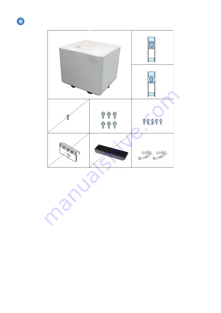
   [1] POD Deck Lite x1

   [6] Screw
       (Binding;M4x5) x5

   [7] Door Stopper x1

   [4] Screw
       (P Tightening;M3x8) x1

   [5] Screw
       (RS Tightening;M4x8) x6

   [2] Latch Plate (Front) x1

   [3] Latch Plate (Rear) x1

   [8] Slope Guide x1

   [9] Wire Saddle x2

Use 3 of them

Use 1 of them

6. Installation

107

Summary of Contents for POD Deck Lite-C1

Page 1: ...Revision 2 0 POD Deck Lite C1 Service Manual ...

Page 2: ...g or short period Canon will issue a new edition of this manual The following paragraph does not apply to any countries where such provisions are inconsistent with local law Trademarks The product names and company names used in this manual are the registered trademarks of the individual companies Copyright This manual is copyrighted with all rights reserved Under the copyright laws this manual ma...

Page 3: ... door and closing the delivery unit door which results in supplying the machine with power 2 In the digital circuits 1 is used to indicate that the voltage level of a given signal is High while 0 is used to indicate Low The voltage value however differs from circuit to circuit In addition the asterisk as in DRMD indicates that the DRMD signal goes on when 0 In practically all cases the internal me...

Page 4: ...ction 12 Overview of the Electrical Circuitry 12 Component Configuration 13 Controls 15 Overview 15 Pickup Feed Control 15 Paper Presence Absence Detection Control 16 Paper Surface Detection Control 16 Lifter Control 17 Remaining Paper Level Detection Control 17 Switching the Paper Size 18 Compartment Open Close Control 19 Air Assist Control 20 Cassette Heater Control Option 22 Power Supply 23 Fan...

Page 5: ...eck Separation Roller 51 Main Units 54 Removing the Pickup Assembly 54 Opening the Compartment 56 Removing the Compartment 56 Heaters 60 Removing the Cassette Heater 60 Removing the Air Heater 61 Solenoids 64 Removing the Compartment Open Solenoid 64 Removing the Deck Pickup Release Solenoid 65 Motors 67 Removing the Deck Lifter Motor 67 Fans 69 Removing the Pickup Release Solenoid Cooling Fan 69 ...

Page 6: ... 105 imageRUNNER ADVANCE 8500 Series 105 imagePRESS C10000VP C8000VP Series 107 Installation Procedure 109 imageRUNNER ADVANCE 8500 Series 109 imagePRESS C10000VP C8000VP Series 119 Checking after Installation 132 imageRUNNER ADVANCE 8500 Series 132 imagePRESS C10000VP C8000VP Series 132 Paper Positioning Check Adjustment Procedure 133 imageRUNNER ADVANCE 8500 Series 133 imagePRESS C10000VP C8000V...

Page 7: ...Safety Precautions Points to Note about Turning Off the Main Power Switch 2 Notes Before Servicing 2 Notes On Assembly Disassembly 2 Points to Note at Cleaning 3 ...

Page 8: ...ed Leakage Breaker Notes Before Servicing CAUTION At servicing be sure to turn off the power source according to the specified steps and disconnect the power plug CAUTION Do not turn off the power switch when downloading is under way Turning off the main power switch while downloading is under way can disable the machine Notes On Assembly Disassembly Follow the items below to assemble disassemble ...

Page 9: ...istor Ensure to use the right screw type when assembling 5 Unless it is specially needed do not operate the device with some parts removed 6 Never remove the paint locked screws when disassembling Points to Note at Cleaning CAUTION When performing cleaning using organic solvent such as alcohol be sure to check that the component of solvent is vaporized completely before assembling Safety Precautio...

Page 10: ...Product Overview 1 Features 5 Specifications 6 Names of Parts 7 Option Construction 10 ...

Page 11: ...of maximum 3 500 sheets 80 g m2 is possible The user can change the stacking paper size easily by the side and rear guide plates with the free stop mechanism and the automatic paper size detection function The envelope can be picked up by attaching the optional Envelope Feeder Attachment The replacement work of the consumable parts is easy 1 Product Overview 5 ...

Page 12: ...X 228 6 mm 1 Custom size 100 X 148 mm to 330 2 X 487 7 mm Different depending on the host machine 1 Only when the optional Envelope Feed er Attachment is installed 2 Do not use the Envelope Feeder At tachment Paper weight 52 g m2 to 300 g m2 Stacking height 385 mm height to bottom of arrow on stack limit label Envelope 100 mm 1 1 When the paper is Yougatanaga 3 the stack height is 160 mm or less S...

Page 13: ...Names of Parts External View Front 5 4 1 2 3 1 Left upper cover 2 Upper cover 3 Compartment open button 4 Front cover 5 Deck release lever 1 Product Overview 7 ...

Page 14: ... Rear 2 1 3 4 5 1 Rear cover 2 Right cover 3 Cassette heater switch 4 Power socket 5 Leakage breaker Internal 4 2 5 1 6 3 1 Product Overview 8 ...

Page 15: ...e plate front 5 Envelope side guide plate front 6 Envelope side guide plate rear Cross Section 2 4 3 1 5 6 1 Deck pull out roller 2 Deck separation roller 3 Deck feed roller 4 Deck pickup roller 5 Blow out vent warm air 6 Blow out vent cool air 1 Product Overview 9 ...

Page 16: ... following optional equipment can install to the this equipment Envelope Feeder Attachment G1 User installation Cassette heater Supplied as the service parts Cassette Heater Envelope Feeder Attachment G1 1 Product Overview 10 ...

Page 17: ...Technology 2 Basic Configuration 12 Controls 15 Upgrading 26 ...

Page 18: ...the DC controller PCB in the host machine The DC controller PCB is equipped with CPU The electric control for the Paper Deck Unit is controlled by the deck driver PCB The deck driver PCB is equipped with EEPROM NOTE The EEPROM stores the following adjustment value ID for model discrimination Small size AD value large size AD value volume value of the free size detection PCB Remaining paper level a...

Page 19: ...tor Sensor Sensor Switch Fan Solenoid Fan ASIC Motor driver DC DC converter Regulator EEPROM Swing driver PCB PCB6 Motor driver Component Configuration Roller Layout 2 4 3 1 1 Deck pull out roller 2 Deck separation roller 3 Deck feed roller 4 Deck pickup roller 2 Technology 13 ...

Page 20: ...own below SR6 SR7 SR6 Deck pull out sensor SR7 Deck pickup sensor Drive Configuration M2 SL2 M1 M4 M3 SL1 M1 Deck pickup motor M2 Deck pull out motor M3 Deck lifter motor M4 Swing motor SL1 Compartment open solenoid SL2 Deck pickup release solenoid 2 Technology 14 ...

Page 21: ...and the drive of the deck pickup motor M1 starts to rotate the pickup roller to pick up paper At this time the deck feed roller and the deck separation roller operate to make sure that only a single sheet of paper is picked up and moved When the deck pull out sensor SR6 detects paper at the time of heavy paper 151 g m2 or more and transparency setting the deck pickup release solenoid SL2 goes on t...

Page 22: ...ction flag Paper Lifter NOTE Service Mode Adjustment of paper surface height Deck Lv2 COPIER ADJUST FEED ADJ DK1 PKLV To adjust the pickup position of the POD Deck Lite Move up When a pickup failure occurs Move down When double feed occurs Setting value 10 to 1 Move down by 1 mm 0 0 mm 1 Move up by 1 mm 2 to 10 Move up by 2 mm Use case When a pickup failure occurs When double feed occurs Caution I...

Page 23: ...s supplied in this condition the lifter moves down to the position where the paper passes through the sensor lever as the paper pushes the sensor lever The lifter keeps moving down until the lifter passes through the deck lifter lower position sensor SR13 which detects maximum paper supply position each time when paper is supplied SR13 SW4 SR9 SR2 SR3 SR4 SR5 SR8 M3 Remaining Paper Level Detection...

Page 24: ...te Sensor name Description Detection method Paper size sensor 1 2 3 SR10 11 12 Size for feed direction ON OFF combination of sensors Paper width detection PCB PCB7 Size for width direction Volume Side guide plate rear Side guide plate front Rear guide plate Paper width detection PCB PCB7 Paper size sensor 1 SR10 Sensor flag Paper size sensor 2 SR11 Paper size sensor 3 SR12 2 Technology 18 ...

Page 25: ... replacing the Paper Width Sensor PCB or registering a new value Caution After execution check the registered value by COPIER ADJUST CST ADJ PDK A5R and write it down on the service label Compartment Open Close Control When the compartment open switch is pushed the deck lifter motor M3 starts to rotate to cause the lifter to move down When 1 sec passes thereafter the compartment open solenoid SL1 ...

Page 26: ...ne executes air assist control The fans FM2 FM3 are combined to blow air against the paper so that the paper is shifted slightly to lose attraction ultimately preventing double feeding To facilitate separation of paper in the high humidity environment an air heater unit H2 is equipped as standard A warming fan FM2 with an air heater blows hot wind against paper to reduce the humidity thus facilita...

Page 27: ... to 105 g m2 Heavy pa per 106 to 150 g m2 Pre punched paper Bond paper Vellum pa per OFF OFF OFF OFF Heavy paper 151 to 300 g m2 Letterhead Textured paper ON 1 ON 1 OFF ON Recycled paper ON ON OFF ON Coated paper ON 1 ON 1 ON 2 ON Special paper Transparency ON ON OFF ON Textured paper ON ON OFF ON Label paper ON ON OFF ON Postcard OFF OFF OFF ON Envelope OFF OFF OFF OFF 1 Switches the wind power o...

Page 28: ...he swing motor M4 drives the shutter to move up and down The direction of air blow against paper changes up or down repeatedly vibrating the paper for easier separation The swing HP sensor SR16 detects a failure of up and down operation of the shutter and the home position of the shutter Paper type Different depending on the host machine Air Assist Control on page 21 Swing motor M4 Swing HP sensor...

Page 29: ... DC power supply is sent to the individual loads from the DC power supply PCB through the deck driver PCB or directly Deck driver PCB PCB1 Air heater driver PCB PCB5 Inlet Leakage breaker ELCB1 AC relay PCB PCB4 DC power supply PCB UN1 RL1 RL2 Cassette heater switch SW2 Cassette heater H1 Air heater H2 RL3 Remote signal Host machine 24䠲 Noise filter 2 Technology 23 ...

Page 30: ...p release solenoid SL2 Jam Detection The machine uses the following 2 sensors to make sure that paper moves smoothly inside it The presence absence of a jam is checked using the signals coming from the host machine at such times as programmed in the host machine When the host machine detects a jam the machine discharges all paper that has been picked up before the jam paper and then stops the oper...

Page 31: ...7 Jam code Jam type Sensor No Sensor name 0A18 Power ON SR6 Deck pull out sensor 0218 Stationary SR6 Deck pull out sensor 0118 Delay SR6 Deck pull out sensor 0117 Delay SR7 Deck pickup sensor 2 Technology 25 ...

Page 32: ...Upgrading Upgrading Since this equipment does not incorporate a CPU upgrade is not required Carry out upgrade on the host machine side 2 Technology 26 ...

Page 33: ...Periodical Service 3 List of Work for Scheduled Servicing 28 ...

Page 34: ... sembly Deck pickup roller FL0 450 0 1 CR 1 000 000sheets CL Timely No LV1 DRBL 2 PD PU RL Removing the Deck Pickup Roller on page 47 2 Deck feed roller FC0 945 0 1 CR 1 000 000sheets CL Timely No LV1 DRBL 2 PD FD RL Removing the Deck Feed Roller on page 49 3 Deck separa tion roll er FC0 963 1 1 CR 1 000 000sheets CL Timely No LV1 DRBL 2 PD SP RL Removing the Deck Separa tion Roller on page 51 4 D...

Page 35: ...sembly Assembly 4 Removing from the Host Machine 30 List of Parts 32 External Covers 42 Consumable Parts and Cleaning Points 47 Main Units 54 Heaters 60 Solenoids 64 Motors 67 Fans 69 Lifter Wire 71 PCBs 84 ...

Page 36: ...OFF the main power on the host machine 2 Turn OFF the cassette heater switch when it is installed 3 Remove the power cord 4 Remove the cable 1 Wire saddle 1 Connector 1x 1x 5 Slide the POD Deck Lite until it stops with holding the release lever 4 Disassembly Assembly 30 ...

Page 37: ...6 Remove the base stay unit 3 Screws 3x 4 Disassembly Assembly 31 ...

Page 38: ... cover Removing the Left Upper Cover on page 42 2 Front cover Removing the Front Cover on page 42 3 Right cover Removing the Right Cover on page 43 4 Rear cover Removing the Rear Cover on page 44 5 Upper cover Removing the Upper Cover on page 45 4 Disassembly Assembly 32 ...

Page 39: ...Reference 1 Deck pickup roller Removing the Deck Pickup Roller on page 47 2 Deck feed roller Removing the Deck Feed Roller on page 49 3 Deck separation roller Removing the Deck Separation Roller on page 51 4 Deck pull out roller 4 Disassembly Assembly 33 ...

Page 40: ...Main Units 1 2 No Name Reference 1 Pickup assembly Removing the Pickup Assembly on page 54 2 Compartment Removing the Compartment on page 56 4 Disassembly Assembly 34 ...

Page 41: ... limit sensor 2 Pickup assembly SR6 Deck pull out sensor Pickup assembly SR7 Deck pickup sensor Pickup assembly SR8 Obstacle sensor SR9 Compartment open close sensor SR10 Paper size sensor 1 Compartment SR11 Paper size sensor 2 Compartment SR12 Paper size sensor 3 Compartment SR13 Deck lifter lower position sensor Compartment SR14 Lifter motor rotation sensor Compartment SR15 Deck paper sensor Pic...

Page 42: ...Main unit Reference SL1 Compartment open solenoid Removing the Compartment Open Solenoid on page 64 SL2 Deck pickup release solenoid Pickup assembly Removing the Deck Pickup Release Solenoid on page 65 4 Disassembly Assembly 36 ...

Page 43: ...M3 No Name Main unit Reference M1 Deck pickup motor M2 Deck pull out motor Pickup assembly M3 Deck lifter motor Compartment Removing the Deck Lifter Motor on page 67 M4 Swing motor Compartment 4 Disassembly Assembly 37 ...

Page 44: ...Main unit Reference FM1 Power supply cooling fan FM2 Warming fan Compartment FM3 Cooling fan Compartment FM4 Pickup release solenoid cool ing fan Removing the Pickup Release Solenoid Cooling Fan on page 69 4 Disassembly Assembly 38 ...

Page 45: ...k Driver PCB on page 84 PCB2 Box driver PCB Compartment PCB3 Swing driver PCB Compartment PCB4 AC relay PCB PCB5 Air heater driver PCB PCB6 Compartment open switch PCB PCB7 Paper width detection PCB Compartment Removing the Paper Width Detection PCB on page 84 UN1 DC power supply PCB 4 Disassembly Assembly 39 ...

Page 46: ...1 No Name Main unit Reference ELCB1 Leakage breaker SW1 Deck connection switch SW2 Cassette heater switch SW3 Deck lifter lower limit switch Compartment SW4 Compartment open close switch SW5 Fan safety switch 4 Disassembly Assembly 40 ...

Page 47: ...unit Reference H1 Cassette heater option Removing the Cassette Heater on page 60 H2 Air heater Compartment Removing the Air Heater on page 61 1 Lifter wire Compartment Removing the Lifter Wire on page 71 4 Disassembly Assembly 41 ...

Page 48: ...moving the Left Upper Cover Procedure 1 Loosen the 2 screws and then remove the Left Upper Cover 2x Removing the Front Cover Preparation 1 Open the Compartment Opening the Compartment on page 56 4 Disassembly Assembly 42 ...

Page 49: ...lines on the 4 marking off lines to fit the Front Cover onto the original position 7x Actions when Replacing the Parts Front Cover on page 90 Removing the Right Cover Preparation 1 Open the Compartment Opening the Compartment on page 56 4 Disassembly Assembly 43 ...

Page 50: ... Procedure 1 Remove the Right Cover 5 Screws 5x Removing the Rear Cover Procedure 1 Remove the Rear Cover 5 Screws 5x 4 Disassembly Assembly 44 ...

Page 51: ... 2 Open the Compartment Opening the Compartment on page 56 3 Remove the Right Cover Removing the Right Cover on page 43 4 Remove the Rear Cover Removing the Rear Cover on page 44 5 Remove the Left Upper Cover Removing the Left Upper Cover on page 42 4 Disassembly Assembly 45 ...

Page 52: ... Procedure 1 Remove the Upper Cover 5 Screws 5x 4 Disassembly Assembly 46 ...

Page 53: ...ller at disassembling assembling 1 Remove the Left Upper Cover Removing the Left Upper Cover on page 42 Procedure 1 Slide the Slide Guide Upper in the direction of the arrow until it stops NOTE When attaching the Left Upper Cover return the Slide Guide Upper to the original position as shown in the figuer 4 Disassembly Assembly 47 ...

Page 54: ...otrusion 2 of the Deck Pickup Roller 1 with the groove 3 of the gear to install the roller 1 2 3 Be sure to insert the Deck Pickup Roller 1 until the claw 2 is hooked 1 2 1x Actions when Replacing the Parts 1 Clear the parts counter Service Mode COPIER COUNTER DRBL 2 PD PU RL LV1 4 Disassembly Assembly 48 ...

Page 55: ...ng assembling 1 Remove the Left Upper Cover Removing the Left Upper Cover on page 42 Procedure 1 Slide the Slide Guide Upper in the direction of the arrow until it stops NOTE When attaching the Left Upper Cover return the Slide Guide Upper to the original position as shown in the figuer 4 Disassembly Assembly 49 ...

Page 56: ...e 2 of the Deck Feed Roller 1 with the protrusion 3 of the Torque Limiter to install the roller 1 2 3 Be sure to insert the Deck Feed Roller 1 until the claw 2 is hooked 1x Actions when Replacing the Parts 1 Clear the parts counter Service Mode COPIER COUNTER DRBL 2 PD FD RL LV1 4 Disassembly Assembly 50 ...

Page 57: ...of the roller at disassembling assembling 1 Remove the Left Upper Cover Removing the Left Upper Cover on page 42 2 Remove the Deck Feed Roller Removing the Deck Feed Roller on page 49 Procedure 1 Slide the Slide Guide Lower in the direction of the arrow and keep it 4 Disassembly Assembly 51 ...

Page 58: ...2 of the Torque Limiter 1 with the spring pin 3 to install the roller 1 2 3 Be sure to align the groove 2 of the Deck Separation Roller 1 with the protrusion 4 of the Torque Limiter 3 to install the roller 1 2 3 4 Be sure to insert the Deck Separation Roller 2 until the claw 1 is hooked 1 2 1x 4 Disassembly Assembly 52 ...

Page 59: ... Actions when Replacing the Parts 1 Clear the parts counter Service Mode COPIER COUNTER DRBL 2 PD SP RL LV1 4 Disassembly Assembly 53 ...

Page 60: ...bly Preparation 1 Open the Compartment Opening the Compartment on page 56 2 Remove the Left Upper Cover Removing the Left Upper Cover on page 42 Procedure 1 Remove the Connector Holder 1 Screw 3 Connectors 1x 3x 4 Disassembly Assembly 54 ...

Page 61: ...igure when replacing the Pickup Assembly 4x NOTE Release the Coupling when the Pickup Assembly is installed CAUTION Be sure to keep opening the Compartment while attaching the Pickup Assembly It may cause not to open the Compartment or damage the Pickup Assembly with closing it Actions when Replacing the Parts Pickup Assembly on page 90 4 Disassembly Assembly 55 ...

Page 62: ...Removing the Compartment Preparation 1 Open the Compartment Opening the Compartment on page 56 Procedure 1 Open the Compartment until it stops while releasing stoppers with pressing the left and right Latches 2 Set sheets of paper approx 6cm under both side of the Compartment to prevent deformation of the wheel plate 4 Disassembly Assembly 56 ...

Page 63: ...move the 2 screws 2 Screws 2x 4 Remove the 3 screws 3 Screws 3x 5 Lift the Compartment and then remove the 2 Guide Pins on the left rail 6 Store the left rail in the POD Deck Lite 4 Disassembly Assembly 57 ...

Page 64: ...7 Lift the Compartment and then remove the 2 Guide Pins on the right rail 8 Store the right rail in the POD Deck Lite 9 Remove the Lifter Motor Assembly Cover 1 Screw 1x 4 Disassembly Assembly 58 ...

Page 65: ...10 Remove the Connection Flat Cable 1 Screw 1 Flat Cable 1x 1x Actions when Replacing the Parts Compartment on page 93 4 Disassembly Assembly 59 ...

Page 66: ...ove the Right Cover Removing the Right Cover on page 43 2 Remove the Rear Cover Removing the Rear Cover on page 44 Procedure 1 Open the Compartment while unlocking the release lever 2 Remove the Heater Connector Cover 1 Claw Claw 4 Disassembly Assembly 60 ...

Page 67: ... 1x 4 Remove the Cassette Heater Assembly 1 Screw 3 Points Cassette Heater Unit Bottom Plate Points 1x Removing the Air Heater Preparation 1 Remove the Rear Cover Removing the Rear Cover on page 44 Procedure 1 Remove the Cable Cover 1 Screw 1x 4 Disassembly Assembly 61 ...

Page 68: ...connector for the Air Heater Assembly 2 Connectors 1 Guide 2x 1x 3 Open the Compartment while unlocking the release lever 4 Remove the Support Cover from top of the Compartment 3 Screws 3x 4 Disassembly Assembly 62 ...

Page 69: ...5 Remove the Air Heater from rear of the Compartment 2 Screws 2x 4 Disassembly Assembly 63 ...

Page 70: ... Remove the Rear Cover Removing the Rear Cover on page 44 Procedure 1 Remove the connector from the Compartment Open Solenoid 1 Connector 1x 2 Mark the line on the plate to reattach the Compartment Open Solenoid onto the original position 4 Disassembly Assembly 64 ...

Page 71: ...n the Release Lever at assembling Removing the Deck Pickup Release Solenoid Preparation 1 Remove the Pickup Assembly Removing the Pickup Assembly on page 54 Procedure 1 Mark the line on the plate to reattach the Deck Pickup Release Solenoid onto the original position 4 Disassembly Assembly 65 ...

Page 72: ...2 Remove the Deck Pickup Release Solenoid 2 Screws 2x 4 Disassembly Assembly 66 ...

Page 73: ...rtment with the open button and then remove all sheets of paper from it 2 Turn OFF the host machine after the Lifter Plate is automatically moved to the bottom 3 Remove the power cord 4 Remove the Compartment Removing the Compartment on page 56 Procedure 1 Remove the Deck Lifter Motor Assembly 2 Connectors 1 Guide 5 Screws 5x 1x 2x 4 Disassembly Assembly 67 ...

Page 74: ...e screws from the access hole of the Lifter Motor Assembly 4 Screws 4x 3 Remove the Deck Lifter Motor Cover 1 Connector 1 Wire Saddle 2 Screws 2x 1x 1x 4 Remove the Deck Lifter Motor 4 Disassembly Assembly 68 ...

Page 75: ...e Rear Cover on page 44 2 Remove the Pickup Assembly Removing the Pickup Assembly on page 54 Procedure 1 Disconnect the connector from rear and then remove the cable from the guide 1 Connector 1 Guide 1x 1x 2 Remove the Pickup Release Solenoid Cooling Fan Assembly 2 Screws 2x 4 Disassembly Assembly 69 ...

Page 76: ...e the Pickup Release Solenoid Cooling Fan 2 Screws 2x CAUTION Align the direction of the arrow on the fan and the fixing plate at assembling of the Pickup Release Solenoid Cooling Fan 4 Disassembly Assembly 70 ...

Page 77: ...sheets of paper from it 2 Turn OFF the host machine after the Lifter Plate is automatically moved to the bottom 3 Remove the power cord 4 Remove the Compartment Removing the Compartment on page 56 5 Remove the Front Cover Removing the Front Cover on page 42 Procedure Deck Lifter Motor Assembly 1 Remove the Deck Lifter Motor Assembly 2 Connectors 1 Guide 5 Screws 5x 1x 2x 4 Disassembly Assembly 71 ...

Page 78: ...ll and large from top of the Compartment 2 Screws 2x 2 Remove the Lifter Wire Shaft Gear 1 E ring 1 Parallel Key 3 Remove the fixing parts from the Lifter Shaft 1 Screw 1 Lifter Wire Fixing Cover 1 Pulley Fixing Plate 1x 4 Disassembly Assembly 72 ...

Page 79: ... and large 2 Parallel Pins 5 Remove the Lifter Wire Front 1 Remove the 2 Lifter Wire Pulleys from top of the Compartment 2 Screws 2x 2 Remove the Lifter Wire Fixing Cover from the Lifter Shaft 1 Screw 1x 4 Disassembly Assembly 73 ...

Page 80: ...ire Rear 1 Slide the Side Guide Plate to the minimum paper size position 2 Put the Lifter Wires through the right and the left lifter holes on the Lifter Plate Long Lifter Wire Put it through the left hole on the plate Short Lifter Wire Put it through the right hole on the plate NOTE Red dot is marked on the Long Lifter Wire 4 Disassembly Assembly 74 ...

Page 81: ...3 Put the Long Lifter Wire through the Small Pulley and then fix it on top left part of the Compartment 1 Screw RS tightening M4x8 1x 4 Disassembly Assembly 75 ...

Page 82: ...e Lifter Wire may be disconnected by wrong assembling Put the Short Lifter Wire between the roller and the fixing plate from the left side Long Lifter Wire Short Lifter Wire Roller Fixing Plate Right Left Front Rear Long Lifter Wire Short Lifter Wire Roller Fixing Plate Right Left Front Rear 4 Disassembly Assembly 76 ...

Page 83: ...asher 1x 6 Attach the Large Pulley and then put the Short Lifter Wire along the groove 1 Parallel Pin CAUTION Put the Short Lifter Wire in the groove R side R R NOTE Pull the Short Lifter Wire from bottom right of the Compartment and attach it without slackness 4 Disassembly Assembly 77 ...

Page 84: ...m bottom left of the Compartment and attach it without slackness 8 Fix the Lifter Wire 1 Pulley Fixing Plate 1 Lifter Wire Fixing Cover 2 Points 1 Screw RS tightening M4x8 CAUTION Do not nip the Lifter Wire between the Lifter Wire Fixing Cover and the pole NOTE Attach the Pulley Fixing Plate to the Small Pulley with fitting the U shaped groove Point Point 1x 4 Disassembly Assembly 78 ...

Page 85: ...and the left lifter holes on the Lifter Plate Long Lifter Wire Put it through the right hole on the plate Short Lifter Wire Put it through the left hole on the plate NOTE Red dot is marked on the Long lifter wire 3 Put the Long Lifter Wire through the Small Pulley and then fix it on top right part of the Compartment 1 Screw RS tightening M4x8 1x 4 Disassembly Assembly 79 ...

Page 86: ... Lifter Wire may be disconnected by wrong assembling Put the Short Lifter Wire between the roller and the fixing plate from the right side Long Lifter Wire Short Lifter Wire Long Lifter Wire Short Lifter Wire Roller Roller Fixing Plate Fixing Plate Right Left Right Left Front Rear Front Rear 4 Disassembly Assembly 80 ...

Page 87: ... Washer 1x 6 Attach the Large Pulley and then put the Short Lifter Wire in the groove 1 Parallel Pin CAUTION Put the Short Lifter Wire in the groove F side F F NOTE Pull the Short Lifter Wire from bottom left of the Compartment to attach it without slackness 4 Disassembly Assembly 81 ...

Page 88: ... the Long Lifter Wire in the groove F side F F NOTE Pull the Long Lifter Wire from bottom right of the Compartment to attach it without slackness 8 Attach the Pulley Fixing Plate 1 E ring NOTE Attach the Pulley Fixing Plate to the Small Pulley with fitting the U shaped groove 4 Disassembly Assembly 82 ...

Page 89: ...9 Attach the Lifter Wire Fixing Cover 1 Screw RS tightening M4x8 CAUTION Do not nip the Lifter Wire between the Lifter Wire Fixing Cover and the pole 1x 4 Disassembly Assembly 83 ...

Page 90: ...river PCB on page 94 Removing the Paper Width Detection PCB Preparation CAUTION The Lifter Plate must be moved to the top before removing the Paper Width Detection PCB 1 Open the Compartment with the open button and then remove all sheets of paper from it 2 Close the Compartment 3 Turn OFF the host machine after the Lifter Plate is automatically moved to the top 4 Remove the power cord 4 Disassemb...

Page 91: ...lide the Side Guide Plate to the maximum paper size position 2 Remove the 2 screws from the Paper Width Detection PCB assembly 2 Screws 2x 3 Remove the Paper Width Detection PCB Upper Cover 4 Disassembly Assembly 85 ...

Page 92: ...4 Remove the Paper Width Detection PCB 1 Connector 1 Wire saddle 1x 1x Actions when Replacing the Parts Paper Width Detection PCB on page 94 4 Disassembly Assembly 86 ...

Page 93: ...Adjustment 5 Adjustment 88 Actions when Replacing the Parts 90 Other Adjustment 96 ...

Page 94: ...5R standard width 11 Service Mode_COPIER OPTION FEED SW DK5 TURN 1 LV1 ON OFF POD Deck Lite Pickup Roller last rotation 12 Service Mode COPIER OPTION FEED SW DK1 AIR LV1 ON OFF of POD Deck Lite air assist 13 Service Mode COPIER OPTION FEED SW DK1 ALVD LV2 Deck Air Float Fan airflow amount downstream 14 Service Mode COPIER OPTION FEED SW DK1 ALVU LV2 Deck Air Float Fan airflow amount upstream 15 Se...

Page 95: ... 94 Other Adjustment No Parts Contents Reference 1 Deck separation roller Adjusting the pressure of the deck separation roller Adjusting the Pressure of the Deck Separation Roller on page 96 2 Deck air float fan Adjusting the deck air float fan airflow amount Adjusting the Paper Separation on page 96 5 Adjustment 89 ...

Page 96: ...bly Actions at Replacement Removing the Pickup Assembly on page 54 Actions after Replacement 1 Remove all sheets of paper from the Compartment and close the Compartment 2 Turn ON the main power 3 Record the setting value on the service mode Service Mode COPIER ADJUST FEED ADJ DK1 PKLV LV1 4 Execute the following item on the service mode Adjustment of paper surface height Deck Service Mode COPIER A...

Page 97: ...ice Mode COPIER FUNCTION CST DK1 SPAD LV1 DK1 SPAD 1 Even DK1 SPAD is set to 1 the value is returned to 0 when the Compartment is opened 6 Check that the position between the Pre Separation Plate and the Lifter Plate is within L 0 5 mm Adjust it on the following procedure in case that it is out of standard L 7 Loosen the 4 screws on the Pre Separation Plate 4x 5 Adjustment 91 ...

Page 98: ...n the Pre Separation Plate and the Lifter Plate within L 0 5 mm NOTE Check the position scale on the left edge of the Pre Separation Plate to record the adjusted value Check that plain paper passes smoothly L 0 5mm 9 Fasten the 2 screws on the left loosened at procedure 7 2x 5 Adjustment 92 ...

Page 99: ...ed at procedure 7 2x 12 Enter the setting value Adjustment of paper surface height Deck recorded at procedure 3 on the service mode Service Mode COPIER ADJUST FEED ADJ DK1 PKLV LV1 Compartment Actions at Replacement Removing the Compartment on page 56 Actions after Replacement 1 Remove all sheets of paper from the Compartment 2 Execute the following item on the service mode Initialization when rep...

Page 100: ...justment the value is stored in the following item Service Mode_COPIER ADJUST CST ADJ PDK A5R LV1 Perform step 4 and following steps only when connected to imageRUNNER ADVANCE 8500 6500 series Entry of the Serial Number If the host machine is supprted The serial number of this machine is memorized by the Deck Driver PCB 1 Enter the serial number by using the following service mode The serial numbe...

Page 101: ... following item on the service mode Service Mode_COPIER FUNCTION CST PDK A5R LV1 7 After automatic adjustment the value is stored in the following item Service Mode_COPIER ADJUST CST ADJ PDK A5R LV1 5 Adjustment 95 ...

Page 102: ...sembly Removing the Pickup Assembly on page 54 Procedure 1 Change the hook position of the pressure spring Pickup failure Hook the spring onto A Double feeding Hook the spring onto B Adjusting the Paper Separation When double feeding occurs adjust the deck air float fan airflow amount on the service mode to set appropriate paper separation Actions at Replacement 1 Remove the Right Cover Removing t...

Page 103: ...OD Deck Lite while checking paper separation from right side NOTE Enter 1 on the following service mode when the fan does not drive automatically in the specific paper type Service Mode COPIER OPTION FEED SW DK1 AIR LV2 5 Adjustment 97 ...

Page 104: ...e compartment 1 2 High pressure air flow amount Some sheets of paper float in a bundle around ceiling in the compartment 1 3 Low pressure air flow amount Small amount of floating paper below 5 paper Floating paper is increased and decreased by 10 sheets of paper 2 Adjust the paper separation on the following procedure in case that it is not optimum air flow amount 5 Adjustment 98 ...

Page 105: ... setting value upstream Service Mode COPIER OPTION FEED SW DK1 ALVU LV2 downstream Service Mode COPIER OPTION FEED SW DK1 ALVD LV2 NOTE Enter the same setting value for upstream and downstream 2 Print out from the POD Deck Lite and check the paper separation Adjust the paper separation again in case that it is not optimum air flow amount 5 Adjustment 99 ...

Page 106: ...llation Procedure 101 Checking before Installation 102 Unpacking Procedure 104 Checking the Contents 105 Installation Procedure 109 Checking after Installation 132 Paper Positioning Check Adjustment Procedure 133 Cassette Heater Assembly 139 ...

Page 107: ...e Illustration The frequently performed operations are described with symbols in this procedure 1x 1x 1x Install Screw Packaged Item Remove Tighten Loosen 1x Connect Connector Disconnect Install Harness Common for Guides and Clamps Remove 1x 1x 1x 1x Connect Power Cord Disconnect Check visually Check the sound Check OFF Cleaning ON Push Power Unused Parts 6 Installation 101 ...

Page 108: ... The minimum space shown in the figure is required for installation and maintenance 800mm or more 500mm or more 800mm or more 1106mm Points to Note on Installation Exercise following caution for installation 1 POD Deck Lite weighs maximum 67 kg When holding the POD Deck Lite at the installation be sure to perform the work in accordance with the standard to handle a heavy load in each country In ad...

Page 109: ...ain Power Check that the main power switch is OFF 1 Turn OFF the main power switch of the host machine 2 Be sure that the control panel display and the main power lamp are both turned OFF and then disconnect the power plug Product Name Safety regulations require the product s name to be registered In some regions where this product is sold the following names may be registered instead F281020 6 In...

Page 110: ...n Remove all packaging tapes and cushioning materials following the unpacking procedure 1 Open the box and remove the accessory box and cushioning materials 2 Open the plastic packing bag Remove the POD Deck Lite from the palette 3 Remove the fixing plate and 2 tags the removed tags fixing plate and screws are not used 2 Screws 2x 4 Remove all packaging tapes 6 Installation 104 ...

Page 111: ...ries 7 Door Stopper x1 4 Screw P Tightening M3x8 x1 9 Wire Saddle x2 1 POD Deck Lite x1 6 Screw Binding M4x5 x5 2 Latch Plate Front x1 3 Latch Plate Rear x1 8 Slope Guide x1 5 Screw RS Tightening M4x8 x6 Use 3 of them Use 1 of them 6 Installation 105 ...

Page 112: ...x1 14 Cassette No Label x1 15 Total Map Label x1 ڧ 22 Extraction Sensor Plate x1 19 Feed Lower Guide Front Fixing Plate x1 20 Feed Lower Guide Rear Fixing Plate x1 for USA 120V for Europe Asia Australia Latin America 230V 1 Use the appropriate power cord by location Make sure not to leave unused power cords at the site Documentations EAC Reference Sheet for Europe Asia Australia and Latin America ...

Page 113: ...D Deck Lite x1 6 Screw Binding M4x5 x5 7 Door Stopper x1 4 Screw P Tightening M3x8 x1 5 Screw RS Tightening M4x8 x6 2 Latch Plate Front x1 3 Latch Plate Rear x1 8 Slope Guide x1 9 Wire Saddle x2 Use 3 of them Use 1 of them 6 Installation 107 ...

Page 114: ...x1 14 Cassette No Label x1 15 Total Map Label x1 ڧ 22 Extraction Sensor Plate x1 19 Feed Lower Guide Front Fixing Plate x1 20 Feed Lower Guide Rear Fixing Plate x1 for USA 120V for Europe Asia Australia Latin America 230V 1 Use the appropriate power cord by location Make sure not to leave unused power cords at the site Documentations EAC Reference Sheet for Europe Asia Australia and Latin America ...

Page 115: ...location imageRUNNER ADVANCE 8500 Series Preparation of the Host Machine 1 Remove the feed cover the removed cover is not used 2 Remove the lower right cover the removed lower right cover and screws are not used 2 Screws 2x 3 Cut the blindfold covers front rear with a side cutter 6 Installation 109 ...

Page 116: ...ch Plates Front Wide Hole Latch Plates Rear Tall Hole Attach the latch plate in the center of the hole 4x Wide Hole RS Tightening M4x8 Tall Hole 5 Remove the connector cover from rear of the host machine the removed connector cover is not used Preparation of the POD Deck Lite 1 Attach the door stopper 1 Screw P tightening screw M3x8 P Tightening M3x8 1x 6 Installation 110 ...

Page 117: ...ed 1x 4 Fix the removed screw at procedure 3 to the original position NOTE The screw is used to fix the base stay unit when the POD Deck Lite is transported 1x Connection with the Host Machine 1 Insert screwdrivers into the hole of the rear right side and then release the lever to open the compartment 2 Open the compartment until it stops while releasing stoppers with pressing left and right latch...

Page 118: ...Deck Lite is transported 5 Fix the 2 screws removed at procedure 4 to the original position 2 Screws TP screws M3x6 2x 6 Affix the foreign language label by language over the original label as shown in the figure the remaining labels are not used 7 Affix the paper size overlay label over the original label by language as shown in the figure the remaining labels are not used 8 Close the compartment...

Page 119: ... machine NOTE Do not nip the cable between the POD Deck Lite and the host machine when connecting NOTE When inserting the rear connection pin into the rear latch hole is difficult loosen the 2 screws fixing the latch plate and then adjust the position of the latch plate to fit it in Check that the latch plate is not positioned at an angle when installing 2x 2x 6 Installation 113 ...

Page 120: ...ion b by adjusting the height of the POD Deck Lite with the 2 adjusters Position a 2 fixing screw tapped holes middle of the POD Deck Lite Position b 2 fixing screw tapped holes middle of the bottom right side wheel b a A B Rotate to A direction Ascent Rotate to B direction Descent A B 6 Installation 114 ...

Page 121: ... RS tightening M4x8 Screw B 2 screws loosened at procedure 11 RS Tightening M4x8 2x 2x Fasten 14 Loosen the 2 screws on the 2 front bottom wheels for each and touch them to the floor 4 Screws Loosen 4x 15 Fasten the 2 screws loosened at procedure 14 4 Screws Fasten 4x 6 Installation 115 ...

Page 122: ...at the bottom 2 is 2mm shorter than the top 1 When relocating the POD Deck Lite re adjust the gap in parallel 2mm 1 2 17 Attach the wire saddle to the hole on rear side of the POD Deck Lite and then clamp the cable with it 1 Wire saddle 1x 18 Connect the lattice connector with the host machine 1x 19 Connect the power cord to the inlet of the POD Deck Lite and then plug it to the external source CA...

Page 123: ...ater in high humidity or low temperature environment 22 Turn ON the main power on the host machine 23 Press the open button of the POD Deck Lite to open the compartment 24 Press the relay paper sensor until the lifter reaches to the bottom position 6 Installation 117 ...

Page 124: ...ts of paper in the compartment and close it 27 Affix the cassette No label 5 the remaining labels are not used 28 Affix the paper size label on the size plate the remaining labels are not used 8 6 2 2 2 2 PP 75 75 PP 65 PP 29 Insert the size plate prepared at procedure 28 to the media plate holder 6 Installation 118 ...

Page 125: ...g the button 2 Remove the 2 screws from the vertical path cover the removed screws are not used 2 Screws 2x 3 Remove the outer cover from the vertical path cover the removed outer cover is not used 4 Remove the front rear blindfold covers the removed front rear blindfold covers are not used 6 Installation 119 ...

Page 126: ...d rear Latch Plate Front Wide Hole Latch Plate Rear Tall Hole Fit the latch plate in the center of the tall hole 4x Wide Hole RS Tightening M4x8 Tall Hole 6 Remove the main station lower right cover the removed cover and screws are not used 2 Screws 2x 7 Remove the cover plate the detached plate and the removed screws are not used 2 Screws 2x 6 Installation 120 ...

Page 127: ...paration of the POD Deck Lite 1 Remove the screw and spacer from the base stay unit Push the POD Deck Lite until it stops while holding the base stay unit the removed screw is used at procedure 2 and the removed spacer is not used 1x 2 Fix the removed screw at procedure 1 to the original position NOTE The screw is used to fix the base stay unit when the POD Deck Lite is transported for relocation ...

Page 128: ...t and right latches 3 Remove the sheet and tapes from the compartment 4 Remove the stay guide Removed 2 screws are used at procedure 5 Removed 1 screw and the stay guide are used at procedure 29 3 Screws 3x NOTE The removed screw is used to fix the stay guide when the POD Deck Lite is transported for relocation 5 Fix the 2 screws removed at procedure 4 to the original position 2 Screws TP screws M...

Page 129: ...t used 7 Affix the paper size overlay label by language over the original label as follows in the figure the remaining labels are not used 8 Affix the total map label b on the base stay unit while fitting it to the marking off line the remaining label is not used a b 9 Close the compartment 6 Installation 123 ...

Page 130: ...s are used at procedure 11 The removed wheel guide plates are not used 2x 11 Attach the 2 marked B wheel guide plates bundled in the host machine with screws removed at procedure 10 2x 12 Move the 2 positioning pins as shown in the figure 2x 2x 6 Installation 124 ...

Page 131: ... host machine NOTE Do not nip the cable between the POD Deck Lite and the host machine when connecting NOTE When inserting the rear connection pin into the rear latch hole is difficult loosen the 2 screws fixing the latch plate and then adjust the position of the latch plate to fit it Check that the latch plate is not positioned at an angle when installing 6 Installation 125 ...

Page 132: ...ion b by adjusting the height of the POD Deck Lite with the 2 adjusters Position a 2 fixing screw tapped holes middle of the POD Deck Lite Position b 2 fixing screw tapped holes middle of the bottom right side wheel b a A B Rotate to A direction Ascent Rotate to B direction Descent A B 6 Installation 126 ...

Page 133: ...Screw B Screw A Supplied 2 Screws RS tightening M4x8 Screw B 2 screws loosened at procedure 15 RS Tightening M4x8 2x 2x Fasten 18 Loosen the 2 screws on the 2 front bottom wheels for each and touch them to the floor 4 Screws Loosen 4x 6 Installation 127 ...

Page 134: ...ure 18 4 Screws Fasten 4x 20 Adjust tilt with the 2 adjusters until a top gap 1 and a bottom gap 2 between the POD Deck Lite and the host machine are same width Rotate to A direction Ascent Rotate to B direction Descent 1 2 6 Installation 128 ...

Page 135: ... parallel 2mm 1 2 21 Connect the lattice connector with the host machine 22 Attach the wire saddle to the hole on rear side of the POD Deck Lite and then clamp the cable with it 1 Wire saddle 1x 23 Connect the power cord to the inlet of the POD Deck Lite and then plug it to the external source CAUTION Make sure that the power cord is fully connected to the outlet If the connection is incomplete sm...

Page 136: ...ater in high humidity or low temperature environment 26 Turn ON the main power on the host machine 27 Press the open button of the POD Deck Lite to open the compartment 28 Press the relay paper sensor until the lifter reaches to the bottom position 6 Installation 130 ...

Page 137: ...ts of paper in the compartment and close it 31 Affix the cassette No label 3 the remaining labels are not used 32 Affix the paper size label on the size plate the remaining labels are not used 8 6 2 2 2 2 PP 75 75 PP 65 PP 33 Insert the size plate prepared at procedure 32 to the media plate holder 6 Installation 131 ...

Page 138: ...r Guide Rear Fixing Plate 1pc 20 Wire Saddle 1pc imagePRESS C10000VP C8000VP Series Disposal Parts 1 Following disposal parts are remained after the installation procedure 1 Screw Binding M4x5 2pcs 2 Screw TP M4x8 2pcs 3 Screw RS Tightening M4x8 2pcs 4 Screw P Tightening M3x8 1pc 5 Vertical Path Cover 1pc 6 Blindfold Cover 2pcs 7 Connector Cover 1pc 8 Main Station Lower Right Cover 1pc 9 Total Map...

Page 139: ...T FEED ADJ ADJ DK LV1 NOTE Setting range 20 to 20 0 1mm by 1 setting value L1 is increased 0 1mm by setting value 1 L1 is increased Image moves to the right L1 is decreased Image moves to the left 2 Exit service mode 3 Print sheets of paper from POD Deck Lite and then check that L1 is 2 5 1 5mm Execute manual adjustment as follows when it is out of standard Adjustment Procedure manual 1 Press the ...

Page 140: ...front A When L1 is small move the latch plate to rear B A B 2x Fasten 5 Loosen the 2 screws at the latch plate on the left side of the compartment 2 Screws 2x Loosen 6 Move the latch plate in the same scale position as procedure 4 and then fasten the 2 screws 1 scale 1mm 2x ࡵࡿ Fasten 7 Move the front cover fitting to the amount of the latch plate adjustment Refer to the next item Front Cover Posit...

Page 141: ... case that it is out of standard Front Cover Positioning Adjustment 1 Check that the gap is 4 1mm between the front cover and upper cover the front cover and right cover 4 1mm 4 1mm NOTE Loosen the 7 screws on the front cover to adjust the gap in 4 1mm Fasten 7x Loosen 7x 6 Installation 135 ...

Page 142: ... adjustment as follows when it is out of standard L1 Adjustment Procedure manual 1 Press the open button of the POD Deck Lite to open the compartment 2 Open the compartment until it stops while releasing stoppers with pressing left and right latches 3 Loosen the 2 screws at the latch plate on the right side of the compartment 2 Screws Loosen 2x 6 Installation 136 ...

Page 143: ... on the left side of the compartment 2 Screws 2x Loosen 6 Move the latch plate in the same scale position as procedure 4 and then fasten the 2 screws 1 scale 1mm 2x ࡵࡿ Fasten 7 Move the front cover fitting to the amount of the latch plate adjustment Refer to the next item Front Cover Positioning Adjustment for detail 8 Close the compartment 9 Print sheets of paper from the POD Deck Lite Check that...

Page 144: ...stment 1 Check that the gap is 4 1mm between the front cover and upper cover the front cover and right cover 4 1mm 4 1mm NOTE Loosen the 7 screws on the front cover to adjust the gap in 4 1mm Fasten 7x Loosen 7x 6 Installation 138 ...

Page 145: ...r Harness X1 4 Switch Unit X 1 5 Wire Saddle X 1 No Parts name Parts Number Q ty 1 Cassette Heater Assem bly FM1 D634 000 1pc 2 Screw TP M3x6 XB6 7300 605 1pc 3 Cassette Heater Harness 120V FM1 E857 000 1pc Cassette Heater Harness 230V FM1 E858 000 1pc 4 Switch Unit FM1 E859 000 1pc 5 Wire Saddle WT2 6108 000 1pc Check the parts numbers on the current parts catalogue as the above parts numbers may...

Page 146: ...x 2 Open the Compartment while unlocking the release lever 3 Remove the Right Cover 5 Screws 5x 4 Open the Compartment until it stops while releasing stoppers with pressing the left and right Latches 5 Remove the Heater Connector Cover the removed cover is used at procedure 8 2 Protrusions 1 Claw Claw Protrusion 6 Installation 140 ...

Page 147: ...M3x6 Base Plate Boss TP M3x6 7 Connect the connector to the POD Deck Lite 1x 8 Install the Heater Connector Cover removed at procedure 5 2 Protrusions 1 Claw Claw Protrusion 9 Install the Cassette Heater Harness 3 Reuse bands 2 Connectors 2x 6 Installation 141 ...

Page 148: ...om ON 11 Attach the wire saddle 1 Wire saddle 12 Fix the Switch Unit Harness as follows 2 Wire saddles 1 Connector 2x 1x 13 Attach the external covers 14 Connect the POD Deck Lite with the host machine 15 Connect the cable 1 Wire saddle 1 Connector 1x 1x 6 Installation 142 ...

Page 149: ...external source CAUTION Make sure that the power cord is fully connected to the outlet If the connection is incomplete smoke or fire may occur 17 Check that the circuit breaker is ON 18 Turn ON the Cassette Heater Switch 19 Turn ON the main power of the host machine 6 Installation 143 ...

Page 150: ...APPENDICES Service Tools 145 General Circuit Diagram 146 ...

Page 151: ...yl alcohol Alcohol Cleaning e g metal oil or toner stain Fluoride family hydrocarbon Chlorine fam ily hydrocarbon Alcohol Do not bring near fire Procure locally Substitute MEK Lubricating oil EM 50L Lubrication e g gears Special oil Special solid lubricating agent Lithium soap Dow Corning Tool No HY9 0007 Lubricating oil Lubrication e g drive areas friction areas Silicone oil FLOIL G5000 H Tool No...

Page 152: ... 1 J404 J710DH 1 2 J710D 2 1 J1 1 2 3 J708 3 4 5 6 1 2 J745 3 4 5 6 1 2 J740 SOLD4 SOLD5 SOLD3 2 1 J403 2 1 J760 8 1 2 3 4 5 6 7 J7 3 4 5 6 1 2 J4 8 1 2 3 4 5 6 7 9 10 J6 1 2 3 4 5 J8 J700LH 14 13 12 11 8 1 2 3 4 5 6 7 9 10 J716 2 3 4 1 J700L 2 3 4 1 J700D 1 2 3 J407D 8 1 2 3 4 5 6 7 J201 2 1 J761 3 4 5 6 2 1 J712 MT2 4 5 3 2 1 J715 SOLD2 2 3 4 1 J402 MT1 SOLD1 3 4 5 6 1 2 J711 1 2 3 J704 1 2 3 J7...

Page 153: ...3 4 1 J504 15 14 13 12 11 10 9 8 2 1 3 4 5 6 7 J724D 1 2 3 J729 1 2 3 J721D 1 2 3 J721L J721DH 1 2 3 4 J719 50 49 24 38 36 34 32 30 28 26 20 18 16 1 2 3 4 5 6 7 8 9 10 11 13 15 17 19 21 23 25 27 29 31 33 35 37 12 14 22 40 39 41 43 45 47 42 44 46 48 J301 MT4 MT3 2 3 4 1 J405 2 1 J717 2 1 J718L 2 1 J718D J718LH 2 1 J305 2 1 J755L 2 3 4 1 J CN4 2 1 J755D 2 1 J728L 2 1 J603D 2 1 J728D J750DH 2 3 4 1 J...

Page 154: ...0D J780DH J770DH 9 8 2 3 4 5 6 1 7 J770D J734LH 1 2 J734D 2 1 J734L 1 2 3 4 5 6 7 8 9 10 12 13 14 15 16 17 18 19 20 11 21 J302 1 2 3 J306 9 8 2 3 4 5 6 1 7 J770L 1 2 3 J725 1 2 3 J728 1 2 3 J727 1 2 3 J726 1 2 3 J731D 1 2 3 J733 SOLD6 SOLD7 PCB2 Deck driver PCB SR15 Deck paper sensor SR10 Paper size sensor 1 SR11 Paper size sensor 2 SR12 Paper size sensor 3 SR14 Lifter motor rotation sensor SW3 De...

Reviews: