background image

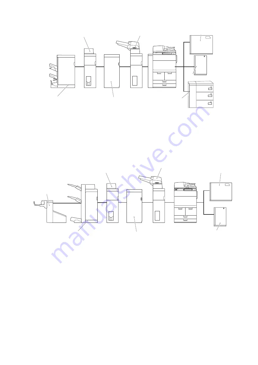
■ For imageRUNNER ADVANCE C7500 Series

Document Insertion Unit-N1

Multi Function 

Professional Puncher-A1

Paper Folding Unit-J1

Staple Finisher-X1

/Booklet Finisher-X1

Paper Deck Unit-E1

Multi Drawer PD-C1

POD Deck Lite-C1

1. POD Deck Lite-C1/ Paper Deck Unit-E1/ Multi-drawer Paper Deck-C1
2. Document Insertion Unit-N1
3. Multi Function Professional Puncher-A1
4. Paper Folding Unit-J1
5. Staple Finisher-X1 / Booklet Finisher-X1

■ For imageRUNNER ADVANCE 8500 Series

• imageRUNNER ADVANCE 8505/8585/8595

Paper Deck Unit-E1

POD Deck Lite-C1

Staple Finisher-W1

/Booklet Finisher-W1

Document Insertion Unit-N1

Multi Function 

Professional Puncher-A1

Paper Folding Unit-J1

Booklet 

Trimmer-D1

1. POD Deck Lite-C1 / Paper Deck Unit-E1
2. Document Insertion Unit-N1
3. Multi Function Professional Puncher-A1
4. Paper Folding Unit-J1
5. Staple Finisher-W1 / Booklet Finisher-W1
6. Booklet Trimmer-D1

6. Installation

112

Summary of Contents for Paper Folding Unit-J1

Page 1: ...Revision 3 0 Paper Folding Unit J1 Service Manual ...

Page 2: ...g or short period Canon will issue a new edition of this manual The following paragraph does not apply to any countries where such provisions are inconsistent with local law Trademarks The product names and company names used in this manual are the registered trademarks of the individual companies Copyright This manual is copyrighted with all rights reserved Under the copyright laws this manual ma...

Page 3: ... door and closing the delivery unit door which results in supplying the machine with power 2 In the digital circuits 1 is used to indicate that the voltage level of a given signal is High while 0 is used to indicate Low The voltage value however differs from circuit to circuit In addition the asterisk as in DRMD indicates that the DRMD signal goes on when 0 In practically all cases the internal me...

Page 4: ... 13 Functional Configuration 13 Electric Circuit Overview 13 Component Configuration 14 Drive Configuration 16 Operation Mode Overview 16 Controls 25 Outline of operations 25 Detecting Jams 52 Power Supply 54 Upgrading 55 Upgrading 55 3 Periodical Service 56 List of Work for Scheduled Servicing 57 4 Disassembly Assembly 59 List of Parts 60 List of Parts 60 Consumable Parts Requiring Periodic Repla...

Page 5: ... M8 80 Removing the C fold Stopper Motor M9 81 Removing the Leading Edge Pushing Guide Motor M10 81 Removing the Inlet Motor 2 M12 82 Removing the Outlet Motor 2 M13 83 Removing the Outlet Motor 1 M14 84 Removing the Folding Position Adjustment Motor M15 85 PCBs 86 Removing the Folder Controller PCB 86 Others 88 Removing the Delivery Feed Roller 88 5 Adjustment 89 Overview 90 Adjustment and Functi...

Page 6: ...ipment 124 Connecting to Upstream Equipment 130 Connecting the Interface Cable 131 Connecting the Intermediate Power Cable 133 Connecting the Shunt Cable 135 Attaching the Label 139 Adjustment 141 Height Inclination Checking and Adjustment 141 Making Checks after Completion of Installation 150 Disposal Parts 150 Operation Checks 151 APPENDICES 152 Service Tools 153 Special Tools 153 Solvents and O...

Page 7: ...Safety Precautions Points to Note About Turning Off the Main Power Switch 2 Notes Before Servicing 2 Points to Note at Cleaning 2 Notes On Assembly Disassembly 2 ...

Page 8: ...n disable the machine Points to Note at Cleaning CAUTION When performing cleaning using organic solvent such as alcohol be sure to check that the component of solvent is vaporized completely before assembling Notes On Assembly Disassembly Follow the items below to assemble disassemble the device 1 Disconnect the power plug to avoid any potential dangers during assembling disassembling works 2 If n...

Page 9: ...Product Overview 1 Outline 4 Specifications 5 Names of Parts 9 ...

Page 10: ...Outline Features Five kinds of the paper folding processing are possible Fold types Z fold C fold outer three fold four fold two fold 1 Product Overview 4 ...

Page 11: ...section All substrates host machine supports Paper weighing capacity Z fold C fold Outer three fold Two fold 52g m2 to 105g m2 Four fold 52g m2 to 90g m2 Feed section 52 g m2 to 350 g m2 Different depending on the host machine Folding delivery tray stacking capacity C fold Loading height 60mm equivalent to 40 sheets Equivalent of 81 4g m2 paper Outer three fold Loading height 60 mm equivalent to 4...

Page 12: ...m 104 0 108 0mm A4R 71 3 75 2mm 73 3 77 2mm 11x17 105 0 109 0mm 107 0 111 0mm LGL 86 0 90 0mm 88 0 92 0mm LTR R 66 8 70 7mm 68 8 72 7mm Two fold T2 T1 T4 T3 Standard T2 Dimensions A4R 146 5 150 5mm LTR R 137 5 141 5mm Four fold F2 F1 F4 F3 T2 T1 T3 1 Product Overview 6 ...

Page 13: ...ength 4 1 2 0mm User adjustment is available Z3 Z4 oblique fold Within 1 5mm Z5 fold height Within 15mm T1 fold 0 2 0mm 3 5mm Reference value T2 overall length Line length 2 2 0mm 3 5mm User adjustment is available T3 oblique fold 1 5mm 2 5mm T4 fold height Within 10mm Z fold Two fold paper delivery performance Delivery Outlet side registration Within 3 5mm Delivery Outlet Cross feed Within 2 5mm ...

Page 14: ...ngth Line length 3 1 5 2 0mm C4 C5 oblique fold Within 1 5mm C6 fold stacking capacity Max 40 sheets Equivalent of 80g m2 paper O1 fold 2 5 2 0mm O2 fold 2 0 2 0mm O3 overall length Line length 3 1 5 2 0mm O4 O5 oblique fold Within 1 5mm O6 fold stacking capacity Max 40 sheets Equivalent of 80g m2 paper The value in is for LGL 1 Product Overview 8 ...

Page 15: ...Names of Parts External View Front Upper cover Front cover Folding delivery tray Folding Unit Rear Leakage breaker Rear cover Rear Upper cover 1 Product Overview 9 ...

Page 16: ... Internal Feed guide Right folding feed guide Inlet feed guide Left folding feed guide left 1 Product Overview 10 ...

Page 17: ...ding roller 2 4 Feed roller 2 15 Registration roller 5 Leading edge stopper 16 Delivery feed roller 5 6 Folding roller1 17 Trailing edge stopper 7 Leading edge pushing guide 18 Delivery feed roller 6 8 Folding roller3 19 Delivery feed roller 7 9 Delivery feed roller 1 20 Delivery feed roller 8 10 Delivery feed roller 2 21 Delivery roller 11 Delivery feed roller 3 1 Product Overview 11 ...

Page 18: ...Technical Explanation 2 Basic Configuration 13 Controls 25 Upgrading 55 ...

Page 19: ...ipment is controlled by the folder controller PCB The folder controller PCB has a CPU The CPU on the controller controls DC loads such as motors and solenoids at the predetermined timings according to the signals from the sensors and the finisher The folder controller PCB reports the information about the sensors to the finisher through serial communication Finisher Folder controller PCB Motor Sol...

Page 20: ...roller 2 15 Registration roller 5 Leading edge stopper 16 Delivery feed roller 5 6 Folding roller1 17 Trailing edge stopper 7 Leading edge pushing guide 18 Delivery feed roller 6 8 Folding roller3 19 Delivery feed roller 7 9 Delivery feed roller 1 20 Delivery feed roller 8 10 Delivery feed roller 2 21 Delivery roller 11 Delivery feed roller 3 Sensor Layout It describes only sensors on the feed pat...

Page 21: ...2 S20 Inlet sensor S21 Delivery sensor 2 S22 Delivery sensor 1 S27 Folding tray paper sensor S30 Slowdown timing sensor S31 Release timing sensor S32 Folding position sensor S33 Upper stopper paper sensor 2 Technical Explanation 15 ...

Page 22: ... motor SOL2 Through Fold Branch Solenoid M11 Folding feed motor SOL3 Fold Separation Solenoid M12 Inlet motor 2 SOL4 Folding tray flapper solenoid M13 Outlet motor 2 Operation Mode Overview Z fold operation The Z fold operation is carried out in the following order of steps 1 Registration correction 2 Paper feeding operation 3 Folding operation 4 Delivery operation Operation 1 Registration correct...

Page 23: ...ion sensor 3 Folding operation Gives the paper a first fold by the folding roller 1 and folding roller 2 Folding roller 1 Folding roller 2 Gives the paper a second fold by the folding roller 2 and folding roller 3 as the paper bumps against the leading edge stopper Folding roller 3 Folding roller 2 Leading edge stopper 2 Technical Explanation 17 ...

Page 24: ...n 4 Delivery operation Operation 1 Registration correction Stops the feeding of paper on the registration roller and forms a loop to correct the registration of the paper 2 Paper feeding operation Feeds the paper by a specified time after the paper has passed through the folding position sensor S32 Feeds the paper longer length than the Z fold operation the position on one third of the paper lengt...

Page 25: ...ller 3 Folding roller 2 Leading edge stopper 4 Delivery operation Delivers the paper to the folding delivery tray C fold operation The C fold operation is carried out in the following order of steps 1 Registration correction 2 Paper feeding operation 3 Folding operation 4 Delivery operation Operation 1 Registration correction Stops the feeding of paper on the registration roller and forms a loop t...

Page 26: ... folding roller 1 and folding roller 2 as the paper bumps against the trailing edge stopper Trailing edge stopper Folding roller 1 Folding roller 2 Gives the paper a second fold by the folding roller 2 and folding roller 3 and leading edge pushing guide as the paper bumps against the leading edge stopper Leading edge pushing guide Leading edge stopper Folding roller 3 Folding roller 2 2 Technical ...

Page 27: ...eration 4 Delivery operation Operation 1 Registration correction Stops the feeding of paper on the registration roller and forms a loop to correct the registration of the paper 2 Paper feeding operation Feeds the paper by a specified time after the paper has passed through the folding position sensor S32 Feeds the paper until the position on one two of the paper length S32 Folding position sensor ...

Page 28: ...e paper bumps against the leading edge stopper Folding roller 2 Folding roller 3 Leading edge pushing guide Leading edge stopper 4 Delivery operation Delivers the paper to the folding delivery tray Two fold operation The twofold operation is carried out in the following order of steps 1 Registration correction 2 Paper feeding operation 3 Folding operation 4 Delivery operation Operation 1 Registrat...

Page 29: ...on sensor 3 Folding operation Gives the paper a first fold by the folding roller 1 and folding roller 2 as the paper bumps against the trailing edge stopper Folding roller 2 Folding roller 1 Trailing edge stopper Feeds the paper to the folding roller 2 and folding roller 3 along the leading edge pushing guide moved beforehand Folding roller 2 Folding roller 3 Leading edge pushing guide 2 Technical...

Page 30: ...4 Delivery operation Feeds the paper to the finisher through the delivery path 2 Technical Explanation 24 ...

Page 31: ...d in conjunction with folding roller 2 at the folding operations Leading edge stopper Feeds the paper to the folding roller 2 and folding roller 3 for a second fold as the folding side of the paper bumps against this stopper at the folding operations Trailing edge stopper Feeds the paper to the folding roller 1 and folding roller 2 for a first fold as the paper bumps against the stopper at the C f...

Page 32: ...eding of paper when detecting the paper Fold Operation Sequence Z fold operation sequence When a post handling specification signal Z fold Operation is received during copying The Z fold operation starts The Z fold operation sequence is as follows 1 Registration correction 2 Paper feeding operation 3 Folding operation 4 Delivery operation Operation 2 Technical Explanation 26 ...

Page 33: ...rned on the inlet motor 1 M5 and inlet motor 2 M12 slow down to 650 mm s The folding position adjustment feed clutch CL3 turns on When the paper has been fed 17 6 mm since the release timing sensor S31 turned on the inlet motor 1 M5 and inlet motor 2 M12 stop amount of the registration loop 7 mm Inlet motor 2 Through Fold Branch Solenoid SOL2 M12 Inlet motor 1 M5 Folding feed motor M11 M13 Outlet ...

Page 34: ...o activate the Fold Separation Solenoid SOL3 When the paper has been fed 15 4 mm since the folding position sensor S32 turned on the folding position adjustment motor M15 stops Fold Separation Solenoid SOL3 S32 Folding position sensor Trailing edge stopper Folding position adjustment motor M15 Folding position adjustment feed clutch CL3 2 Technical Explanation 28 ...

Page 35: ...SOL3 turned off A loop is formed at the registration roller starting the first fold operation The release timing sensor S31 turns off to turn off the folding position adjustment back clutch CL4 The leading edge of the first fold bumps against the leading edge stopper starting the second fold operation Folding position adjustment motor M15 Folding position adjustment feed clutch CL3 Folding positio...

Page 36: ...nsor 1 S22 turned off the outlet motor 1 M14 and outlet motor 2 M13 drive at the same speed with the host machine for feeding the paper to the finisher The outlet motor 1 M14 stops since the delivery sensor 2 S21 turned off Folding feed motor M11 Folding feed motor M11 S21 Delivery sensor 2 S22 Delivery sensor 1 M13 Outlet motor 2 Outlet motor 1 M14 2 Technical Explanation 30 ...

Page 37: ...e When a post handling specification signal C fold Operation is received during copying C fold operation starts The C fold operation sequence is as follows 1 Registration correction 2 Paper feeding operation 3 Folding operation 4 Delivery operation Operation 2 Technical Explanation 31 ...

Page 38: ...g sensor S30 turned on the drive speed of the inlet motor 1 M5 and inlet motor 2 M12 change to 650 mm s The folding position adjustment feed clutch CL3 turns on When the paper has been fed 17 6 mm since the release timing sensor S31 turned on the inlet motor 1 M5 and inlet motor 2 M12 stop amount of the registration loop 7 mm Inlet motor 2 Through Fold Branch Solenoid SOL2 C fold stopper motor M12...

Page 39: ...railing edge passed through the released rollers and 150 ms have passed after the Fold Separation Solenoid SOL3 turned on the Fold Separation Solenoid SOL3 turns off When the paper has been fed 10 0 mm since its trailing edge passed by the trailing edge stopper the folding position adjustment motor M15 stops Folding position adjustment motor Fold Separation Solenoid SOL3 M15 S32 Folding position s...

Page 40: ... folding position adjustment back clutch CL4 The upper stopper paper sensor S33 turns on and the C fold stopper solenoid SOL5 turns off The leading edge of the first fold bumps against the leading edge stopper starting the second fold operation The leading edge pushing guide starts moving 133 ms after the upper stopper paper sensor S33 turned on The upper stopper paper sensor S33 turns off to turn...

Page 41: ...dge pushing guide S31 Release timing sensor Folding position adjustment back clutch CL4 Folding position adjustment motor M15 Fold Separation Solenoid SOL3 S30 Slowdown timing sensor Inlet motor 2 M12 Inlet motor 1 M5 2 Technical Explanation 35 ...

Page 42: ...rns at a speed of 533 pps after elapsing by 100 ms since the folding tray flapper solenoid SOL4 turned off The folding tray HP sensor S28 turns on to stop the folding tray motor M7 Leading edge pushing guide S22 Delivery sensor 1 Folding position adjustment motor M15 Folding tray flapper solenoid SOL4 S32 Folding position sensor Fold Separation Solenoid SOL3 Folding tray motor M7 S28 Folding tray ...

Page 43: ...en a post handling specification signal Outer three fold Operation is received during copying outer three fold operation starts The outer three fold operation sequence is as follows 1 Registration correction 2 Paper feeding operation 3 Folding operation 4 Delivery operat Operation 2 Technical Explanation 37 ...

Page 44: ...ive speed of the inlet motor 1 M5 and inlet motor 2 M12 change to 650 mm s The folding position adjustment feed clutch CL3 turns on When the paper has been fed 17 6 mm since the release timing sensor S31 turned on the inlet motor 1 M5 and inlet motor 2 M12 stop amount of the registration loop 7 mm Inlet motor 2 Through Fold Branch Solenoid SOL2 M12 Inlet motor 1 M5 Folding feed motor M11 S30 Slowd...

Page 45: ... to activate the Fold Separation Solenoid SOL3 When paper has been fed 40 5 mm since the folding position sensor S32 turned on the folding position adjustment motor M15 stops Fold Separation Solenoid SOL3 S32 Folding position sensor Trailing edge stopper Folding position adjustment motor M15 Folding position adjustment feed clutch CL3 2 Technical Explanation 39 ...

Page 46: ...ration roller starting the first fold operation The release timing sensor S31 turns off to deactivate the folding position adjustment back clutch CL4 The leading edge of the first fold bumps against the leading edge stopper starting the second fold operation Flapper Solenoid SOL4 turns on after Upper Stopper Paper Sensor S33 turned off Folding position adjustment motor M15 Folding position adjustm...

Page 47: ...㸦Folding tray flapper solenoid 㸧 SOL4 㸦Entrance motor 2㸧 M12 㸦Entrance motor 1㸧 M5 㸦Fold feed motor㸧 M11 Folding feed motor Inlet motor 2 M12 Upper stopper motor M8 M11 2 Technical Explanation 41 ...

Page 48: ...ff The folding tray motor M7 starts turning at a speed of 533 pps after elapsing by 100 ms since the folding tray flapper solenoid SOL4 turned off The folding tray HP sensor S28 turns on to stop the folding tray motor M7 Folding tray flapper solenoid SOL4 S22 Delivery sensor 1 Folding tray flapper solenoid SOL4 Folding tray motor M7 S28 Folding tray HP sensor Four fold operation sequence 2 Technic...

Page 49: ...d 233 0 mm since the slowdown timing sensor S30 turned on the drive speed of the inlet motor 1 M5 and inlet motor 2 M12 change to 650 mm s The folding position adjustment feed clutch CL3 turns on For plain paper the inlet motor 1 M5 and inlet motor 2 M12 stop amount of the registration loop 7 mm when the paper has been fed 17 6 mm since the release timing sensor S31 turned on For thin paper the in...

Page 50: ...ns at a speed of 400 mm s Without thin paper The folding position sensor S32 turns on to activate the Fold Separation Solenoid SOL3 When the paper has been fed 10 0 mm since its trailing edge passed through the released rollers and 150 ms have passed after the Fold Separation Solenoid turned on the Fold Separation Solenoid SOL3 turns off When the paper has been fed 10 0 mm since its trailing edge ...

Page 51: ...1 turns off to stop the folding position adjustment motor M15 and turn off the folding position adjustment back clutch CL4 The upper stopper paper sensor S33 turns on to turn off the C fold stopper solenoid SOL5 The leading edge of the first fold bumps against the leading edge stopper starting the second fold operation The leading edge pushing guide starts moving 71 ms after the upper stopper pape...

Page 52: ...er stopper paper sensor S31 Release timing sensor Folding position adjustment back clutch CL4 Folding position adjustment motor M15 Fold Separation Solenoid SOL3 S30 Slowdown timing sensor Inlet motor 2 M12 Inlet motor 1 M5 Folding tray flapper solenoid SOL4 2 Technical Explanation 46 ...

Page 53: ...ding tray flapper solenoid SOL4 turned off When the paper has been fed 366 pls 91 5 mm since the Folding tray HP sensor S21 turned off the motor stops 100 ms later the motor starts at a speed of 300 pps The folding tray HP sensor S28 turns on to stop the folding tray motor M7 Folding tray motor M7 Leading edge pushing guide Folding tray flapper solenoid SOL4 S28 Folding tray HP sensor S22 Delivery...

Page 54: ...en fed 233 0 mm since the slowdown timing sensor S30 turned on the drive speed of the inlet motor 1 M5 and inlet motor 2 M12 change to 650 mm s The folding position adjustment feed clutch CL3 turns on For plain paper the inlet motor 1 M5 and inlet motor 2 M12 stop amount of the registration loop 7 mm when the paper has been fed 17 6 mm since the release timing sensor S31 turned on For thin paper t...

Page 55: ...m s Without thin paper The folding position sensor S32 turns on to activate the Fold Separation Solenoid SOL3 When the paper has been fed 10 0 mm since its trailing edge passed through the released rollers and 150 ms have passed after theFold Separation Solenoid SOL3 turned on theFold Separation Solenoid SOL3 turns off When the paper has been fed 10 0 mm since its trailing edge passed by the trail...

Page 56: ...n The release timing sensor S31 turns off to stop the folding position adjustment motor M15 and turn off the folding position adjustment back clutch CL4 Folding position adjustment motor M15 Folding position adjustment back clutch CL4 CL3 Folding position adjustment feed clutch C fold stopper solenoid SOL5 Trailing edge stopper Folding position adjustment motor M15 Folding position adjustment back...

Page 57: ... delivery sensor 1 S22 turned on the drive speed of the outlet motor 1 M14 and outlet motor 2 M13 change to the same speed with the host machine The Delivery sensor 2 S21 turns off to change the speed of the outlet motor 1 M14 to 400 mm s Outlet motor 2 M13 Outlet motor 1 M14 S22 Delivery sensor 1 Outlet motor 1 M14 S32 Folding position sensor S21 Delivery sensor 2 Fold Separation Solenoid SOL3 Fo...

Page 58: ...nso Detection timing EntryStart time out jam EntryStart OFF is not detected even when the specified time has lapsed since EntryStartAck ON was replied EjectStartAck time out jam EjectStartAck ON is not detected even when the specified time has lapsed since EjectStart ON was reported EjectStartAck OFF is not detected even when the specified time has lapsed since EjectStart OFF was reported Cover op...

Page 59: ...e has lapsed since pulling in of paper by the registra tion roller started Upper stopper paper sensor delay jam S33 The upper stopper paper sensor S33 does not detect paper even when the specified time has lapsed since the fold feed operation star ted Delivery sensor 1 delay jam S22 The delivery sensor 1 S22 does not detect paper even when the specified time has lapsed since the upper stopper pape...

Page 60: ...ly unit is provided with an overcurrent overvoltage protective function to shut off the output voltage automatically when an excessive current or voltage occurs due to a problem on the load side e g short circuiting thus protecting electric circuits Each circuit is provided with a fuse which is blown when an excessive current flows in theAC line thus shutting off the excessive AC current Sensor DC...

Page 61: ...Upgrading Upgrading When upgrading the firmware of the folder controller PCB upgrade from the host machine Refer to the service manual for the host machine as to the detail 2 Technical Explanation 55 ...

Page 62: ...Periodical Service 3 List of Work for Scheduled Servicing 57 ...

Page 63: ...chine paper pass DRBL 2 PF ELM2 Remov ing the Through pass Out let Anti static Needle on page 78 3 Folding Unit Folding position adjustment feed clutch CL3 FK2 4588 1 CR 1 000 000 sheets DRBL 2 PF CL1 Remov ing the Folding Position Adjust ment Feed Clutch CL3 on page 73 4 Folding position adjustment back clutch CL4 FK2 4588 1 CR 1 000 000 sheets DRBL 2 PF CL2 Remov ing the Folding Position Adjust ...

Page 64: ...rors of Release timing sensor 1 CL 200 000 sheets Clean it with a cloth wetted with water and squeezed tightly No 11 Reflection mirrors of Upper stopper paper sensor 1 CL 200 000 sheets Clean it with a cloth wetted with water and squeezed tightly No 12 Reflection mirrors of Folding position sensor 1 CL 200 000 sheets Clean it with a cloth wetted with water and squeezed tightly No 13 Folding roller...

Page 65: ...Disassembly Assembly 4 List of Parts 60 External Internal Covers 64 Main Units 71 Consumable Parts Requiring Periodic Replacement and Cleaning Points 73 Motors 80 PCBs 86 Others 88 ...

Page 66: ...emoving the Front Lower Cover on page 66 3 Rear Upper Cover Removing the Rear Upper Cover on page 64 4 Rear Cover Removing the Rear Cover on page 64 5 Front Inner Cover Removing the Front Inner Cover on page 68 6 Rear Inner Cover Removing the Rear Inner Cover on page 66 7 Right Inner Cover Removing the Right Inner Cover on page 70 4 Disassembly Assembly 60 ...

Page 67: ...oving the Folding Position Adjustment Feed Clutch CL3 on page 73 4 Folding position adjustment back clutch CL4 Removing the Folding Position Adjustment Back Clutch CL4 on page 73 5 Fold Separation Solenoid SOL3 Removing the Fold Separation Solenoid SOL3 on page 75 6 Through Fold Branch Solenoid SOL2 Removing the Through Fold Branch Solenoid SOL2 on page 74 7 C fold stopper solenoid SOL5 Removing t...

Page 68: ...M14 Outlet motor 1 Removing the Outlet Motor 1 M14 on page 84 M15 Folding position adjustment motor Removing the Folding Position Adjustment Motor M15 on page 85 SW1 Front upper cover switch CL3 Folding position adjustment feed clutch Removing the Folding Position Adjustment Feed Clutch CL3 on page 73 CL4 Folding position adjustment back clutch Removing the Folding Position Adjustment Back Clutch ...

Page 69: ...22 S32S31 S23 S25 S26 S33 S30 No Name S20 Inlet sensor S21 Delivery sensor 2 S22 Delivery sensor 1 S23 Upper stopper HP sensor S24 C fold stopper HP sensor S25 Leading edge pushing guide HP sensor S26 Folding tray paper full sensor S27 Folding tray paper sensor S28 Folding tray HP sensor S29 Folding unit sensor S30 Slowdown timing sensor S31 Release timing sensor S32 Folding position sensor S33 Up...

Page 70: ...r upper cover 4 Screws 4x Removing the Rear Cover Preparation 1 Remove the rear upper cover Removing the Rear Upper Cover on page 64 Procedure 1 Remove the rear cover 4 Screws 4x Open the Front cover Procedure 1 Open the front cover as the following figure 4 Disassembly Assembly 64 ...

Page 71: ... cover on page 64 Procedure 1 Holding the jam removal lever open the feed guide Removing the Front Cover Preparation 1 Open the front cover Open the Front cover on page 64 Procedure 1 Remove two resin E rings to remove the front cover 2 E rings 4 Disassembly Assembly 65 ...

Page 72: ...lower cover engage two hooks of the front lower cover to the left and right protrusions of the folding unit Removing the Rear Inner Cover Preparation 1 Open the front cover Open the Front cover on page 64 2 Open the feed guide Open the Feed Guide on page 65 3 Remove the rear upper cover Removing the Rear Upper Cover on page 64 4 Remove the rear cover Removing the Rear Cover on page 64 4 Disassembl...

Page 73: ... Procedure 1 Remove the screws 2 Screws 2x 4 Disassembly Assembly 67 ...

Page 74: ... the way NOTE When installing the rear inner cover insert two hooks 1 of the rear inner cover in the holes of the folding unit 2 2 1 Removing the Front Inner Cover Preparation 1 Open the front cover Open the Front cover on page 64 2 Open the feed guide Open the Feed Guide on page 65 4 Disassembly Assembly 68 ...

Page 75: ... Procedure 1 Draw out the folding unit 2 Lower the lock lever 1 Screw 1x 3 Remove the front inner cover small 2 Screws 2x 4 Disassembly Assembly 69 ...

Page 76: ...en the front cover Open the Front cover on page 64 2 Open the feed guide Open the Feed Guide on page 65 3 Draw out the folding unit Drawing out the Folding Unit on page 71 Procedure 1 Open the right folding feed guide fully 2 Remove the right inner cover 2 Screws 2x 4 Disassembly Assembly 70 ...

Page 77: ...ront cover Open the Front cover on page 64 2 Open the feed guide Open the Feed Guide on page 65 Procedure 1 Draw out the folding unit Removing the Power Supply Unit Base Preparation 1 Remove the rear cover Removing the Rear Cover on page 64 4 Disassembly Assembly 71 ...

Page 78: ... Procedure 1 Release the harness from the wire saddles to remove the power supply unit base 5 Screws 3 Connectors 1 Grounding Wire 5x 10x 3x 4 Disassembly Assembly 72 ...

Page 79: ... 66 Procedure 1 Release the harness from the wire saddles to remove the folding position adjustment feed clutch 1 Connector 1 E rings 1x 2x Actions after Replacement the Parts 1 Clear parts counter Service Mode COPIER COUNTER DRBL 2 PF CL1 Removing the Folding Position Adjustment Back Clutch CL4 Preparation 1 Open the front cover Open the Front cover on page 64 2 Open the feed guide Open the Feed ...

Page 80: ...gh Fold Branch Solenoid SOL2 Preparation 1 Open the front cover Open the Front cover on page 64 2 Open the feed guide Open the Feed Guide on page 65 3 Draw out the folding unit Drawing out the Folding Unit on page 71 4 Remove the front lower cover Removing the Front Lower Cover on page 66 Procedure 1 Release the harness from the wire saddle to remove the Through Fold Branch Solenoid Unit 1 Connect...

Page 81: ...nter Service Mode COPIER COUNTER DRBL 2 PF FL SL Removing the Fold Separation Solenoid SOL3 Preparation 1 Open the front cover Open the Front cover on page 64 2 Open the feed guide Open the Feed Guide on page 65 3 Draw out the folding unit Drawing out the Folding Unit on page 71 4 Remove the right inner cover Removing the Right Inner Cover on page 70 Procedure 1 Release the harness from the wire s...

Page 82: ...OL4 Remove the rear inner cover 1 Remove the rear cover Removing the Rear Cover on page 64 2 Remove the power supply unit base Removing the Power Supply Unit Base on page 71 3 Remove the rear inner cover Removing the Rear Inner Cover on page 66 Procedure 1 After drawing the mark lines around the fixed position of the solenoid release the harness from the wire saddles to remove the folding tray fla...

Page 83: ...unit Drawing out the Folding Unit on page 71 4 Remove the right inner cover Removing the Right Inner Cover on page 70 Procedure 1 Release the harness from the wire saddles to remove the C fold stopper solenoid unit 1 Screws 1 Connector 1x 2x 1x Actions after Replacement the Parts 1 Clear parts counter Service Mode COPIER COUNTER DRBL 2 PF ST SL Removing the Through pass Inlet Antistatic Needle Pre...

Page 84: ...rews 2x Actions after Replacement the Parts 1 Clear parts counter Service Mode COPIER COUNTER DRBL 2 PF ELM1 Removing the Through pass Outlet Antistatic Needle Preparation 1 Open the front cover Open the Front cover on page 64 Procedure 1 Remove the 2 through pass outlet antistatic needles 2 Screws 4 Disassembly Assembly 78 ...

Page 85: ...2x Actions after Replacement the Parts 1 Clear parts counter Service Mode COPIER COUNTER DRBL 2 PF ELM2 4 Disassembly Assembly 79 ...

Page 86: ...1 Procedure 1 Remove the lower cover 2 Screws 2x 2 Remove the folding tray motor 1 Connector 2 Screws 2x 1x Removing the Upper Stopper Motor M8 Preparation 1 Open the front cover Open the Front cover on page 64 2 Open the feed guide Open the Feed Guide on page 65 3 Draw out the folding unit Drawing out the Folding Unit on page 71 4 Remove the front lower cover Removing the Front Lower Cover on pag...

Page 87: ... page 71 4 Remove the right inner cover Removing the Right Inner Cover on page 70 Procedure 1 Rremove the C fold stopper motor 1 Connector 2 Screws 2x 1x Removing the Leading Edge Pushing Guide Motor M10 Preparation 1 Open the front cover Open the Front cover on page 64 2 Open the feed guide Open the Feed Guide on page 65 3 Draw out the folding unit Drawing out the Folding Unit on page 71 4 Remove...

Page 88: ...ration 1 Remove the rear upper cover Removing the Rear Upper Cover on page 64 2 Remove the rear cover Removing the Rear Cover on page 64 3 Remove the rear inner cover Removing the Rear Inner Cover on page 66 Procedure 1 Holding the upper portion of the folding unit pull the folding unit backward 4 Disassembly Assembly 82 ...

Page 89: ...emove the rear upper cover Removing the Rear Upper Cover on page 64 2 Remove the rear cover Removing the Rear Cover on page 64 3 Remove the rear inner cover Removing the Rear Inner Cover on page 66 Procedure 1 Holding the upper portion of the folding unit pull the folding unit backward 4 Disassembly Assembly 83 ...

Page 90: ...emove the rear upper cover Removing the Rear Upper Cover on page 64 2 Remove the rear cover Removing the Rear Cover on page 64 3 Remove the rear inner cover Removing the Rear Inner Cover on page 66 Procedure 1 Holding the upper portion of the folding unit pull the folding unit backward 4 Disassembly Assembly 84 ...

Page 91: ...ver Open the Front cover on page 64 2 Open the Feed Guide Open the Feed Guide on page 65 3 Draw out the Folding Unit Drawing out the Folding Unit on page 71 4 Remove the Front Lower Cover Removing the Front Lower Cover on page 66 Procedure 1 Remove the folding position adjustment motor 1 Connector 2 Screws 1 Spring 2x 1x 4 Disassembly Assembly 85 ...

Page 92: ...ION MISC P P PRINT 2 Turn OFF the main power switch Preparation 1 Remove the rear upper cover Removing the Rear Upper Cover on page 64 Procedure 1 Disconnect all connectors and remove one screw and three locking supports 1 to remove the folder controller PCB All Connector 1 Screw 3 Locking Supports 1x 1 1 Actions after Replacing the Parts 1 Turn ON the main power switch 2 If a message prompting th...

Page 93: ... SORTER ADJUST PF LDRZ2 Service Mode SORTER ADJUST PF LGLZ1 Service Mode SORTER ADJUST PF LGLZ2 Service Mode SORTER ADJUST PFLTRRZ1 Service Mode SORTER ADJUST PFLTRRZ2 Service Mode SORTER ADJUST PF A4RC1 Service Mode SORTER ADJUST PF A4RC2 Service Mode SORTER ADJUST PFLTRRC1 Service Mode SORTER ADJUST PFLTRRC2 Service Mode SORTER ADJUST PF A4R31 Service Mode SORTER ADJUST PF A4R32 Service Mode SOR...

Page 94: ...t cover on page 64 2 Open the feed guide Open the Feed Guide on page 65 3 Draw out the folding unit Drawing out the Folding Unit on page 71 Procedure 1 Remove the left folding feed guide cover 4 Screws 2 Hooks 4x 2x 2 Remove the delivery feed rollers each 2 Springs 4 Disassembly Assembly 88 ...

Page 95: ...Adjustment 5 Overview 90 Major Adjustment 93 Action on parts replacement 105 ...

Page 96: ...gs Registration menu is inadequate 12 Service Mode SORTER ADJUST PFLTRRZ2 Adjustment of LTRR Z fold position 2nd When the fold position adjustment in Set tings Registration menu is inadequate 13 Service Mode SORTER ADJUST PF A4RC1 Adjustment of A4R C fold position 1st When the fold position adjustment in Set tings Registration menu is inadequate 14 Service Mode SORTER ADJUST PF A4RC2 Adjustment of...

Page 97: ...he Folder Controller PCB of the Paper Folding Unit 34 Service Mode SORTER FUNCTION FLD BK W Controller PCB backup data write When replacing the Folder Controller PCB of the Paper Folding Unit 35 Service Mode SORTER FUNCTION PF CON Controller PCB RAM clear When clearing RAM data of the Folder Controller PCB on Paper Folding Unit Basic Adjustment No Items Refer to 1 Z fold Outer three fold 1st fold ...

Page 98: ...fter replacement the parts exe cute the Service Mode shown be low Service Mode SORTER FUNCTION PF SENS3 5 Actions when Replacing the Upper Stop per Path Sensor After replacement the parts exe cute the Service Mode shown be low Service Mode SORTER FUNCTION PF SENS4 5 Adjustment 92 ...

Page 99: ...LTR R 66 8 70 7mm 68 8 72 8mm Outer three fold O3 O1 O2 O6 O4 O5 Standard O3 Dimensions A4R 98 5 102 5mm LTR R 92 6 96 5mm Item Accuracy of A zone 15 27 5 deg C 25 75 RH Remarks Z1 fold Line length 4 1 2 0mm Z2 fold Line length 4 1 2 0mm User adjustment is available Z3 Z4 oblique fold Within 1 5mm Z5 fold height Within 15mm Z fold Two fold paper delivery performance Delivery Outlet side registrati...

Page 100: ...length 3 1 5 2 0mm O4 O5 oblique fold Within 1 5mm O6 fold stacking capacity Max 40 sheets Equivalent of 80g m2 paper 1 Open the front cover and then open the feed guide 2 Draw out the folding unit 3 Open the right folding feed guide fully and loosen the screw 1x 5 Adjustment 94 ...

Page 101: ...4 Open the left folding feed guide and loosen the screw 1x 5 Remove two screws to remove the face plate 2 Screws 2x 6 Loosen two screws 2x 5 Adjustment 95 ...

Page 102: ...wn NOTE There is the case that an adjustment screw is fixed with adhesive but may turn it only at the time of adjustment B A B A 8 After finishing the adjustment tighten four loosened screws and then attach the face plate by two screws Z fold Outer three fold C fold 2nd fold inclination adjustment Leading edge stopper inclination adjustment Standard value Z fold Z2 Z3 Z4 Z1 Z5 Standard Z1 Dimensio...

Page 103: ... A zone 15 27 5 deg C 25 75 RH Remarks Z1 fold Line length 4 1 2 0mm Z2 fold Line length 4 1 2 0mm User adjustment is available Z3 Z4 oblique fold Within 1 5mm Z5 fold height Within 15mm Z fold Two fold paper delivery performance Delivery Outlet side registration Within 3 5mm Delivery Outlet Cross feed Within 2 5mm 100mm C1 fold 2 5 2 0mm C2 fold 2 0 2 0mm C3 overall length Line length 3 1 5 2 0mm...

Page 104: ...H Remarks O3 overall length Line length 3 1 5 2 0mm O4 O5 oblique fold Within 1 5mm O6 fold stacking capacity Max 40 sheets Equivalent of 80g m2 paper 1 Open the front cover and then open the feed guide 2 Draw out the folding unit 5 Adjustment 98 ...

Page 105: ...rn the adjusting screw clockwise B The rear side of the leading edge stopper moves down NOTE There is the case that an adjustment screw is fixed with adhesive but may turn it only at the time of adjustment B A B A Z fold Two fold paper skew adjustment Delivery guide protective sheet protrusion adjustment Standard value Z fold Z2 Z3 Z4 Z1 Z5 Standard Z1 Dimensions Z2 Dimensions A3 102 0 106 0mm 104...

Page 106: ... Line length 4 1 2 0mm User adjustment is available Z3 Z4 oblique fold Within 1 5mm Z5 fold height Within 15mm T1 fold 0 2 0mm 3 5mm Reference value T2 overall length Line length 2 2 0mm 3 5mm User adjustment is available T3 oblique fold 1 5mm 2 5mm T4 fold height Within 10mm Z fold Two fold paper delivery performance Delivery Outlet side registration Within 3 5mm Delivery Outlet Cross feed Within...

Page 107: ...the delivery guide and the protective sheet to adjust the Z fold Two fold paper skew 2x C fold Two fold Four fold 1st fold inclination adjustment Trailing edge stopper inclination Standard value C fold C3 C1 C2 C6 C4 C5 Standard C3 Dimensions A4R 98 5 102 5mm LTR R 92 6 96 5mm Two fold 5 Adjustment 101 ...

Page 108: ...oblique fold 1 5mm 2 5mm T4 fold height Within 10mm Z fold Two fold paper delivery performance Delivery Outlet side registration Within 3 5mm Delivery Outlet Cross feed Within 2 5mm 100mm F1 fold 2 0 2 0mm 3 5mm F2 overall length Line length 4 1 5 2 0mm User adjustment is available F3 oblique fold 1 5mm 2 0mm F4 fold height Within 30mm Reference value C1 fold 2 5 2 0mm C2 fold 2 0 2 0mm C3 overall...

Page 109: ...ing unit 3 Open the right folding feed guide fully and then remove two screws to remove the right inner cover 2 Screws 2x 3x 4 Disconnect one connector and remove four screws and then release the harness from the harness guide to remove upper paper feed guide 1 Connectors 4 Screws 5 Adjustment 103 ...

Page 110: ...5 4x 1x 1x Loosen fixing screw and then turn the adjustment screw for A direction lower or B direction upper to adjust the inclination of the trailing edge stopper A B A B 2x 5 Adjustment 104 ...

Page 111: ...ch 2 If a message prompting the user to update the version appears press Update to update automatically the version of this equipment NOTE If Skip is selected a message prompting the user to update the version will appear every time when the host machine is started It is possible to set not to display the message by the service mode Level 2 shown below Service Mode_COPIER OPTION FNC SW VER CHNG In...

Page 112: ...DJUST PFLTRRC1 Service Mode SORTER ADJUST PFLTRRC2 Service Mode SORTER ADJUST PF A4R31 Service Mode SORTER ADJUST PF A4R32 Service Mode SORTER ADJUST PFLTRR31 Service Mode SORTER ADJUST PFLTRR32 Service Mode SORTER ADJUST PF A4R41 Service Mode SORTER ADJUST PF A4R42 Service Mode SORTER ADJUST PFLTRR41 Service Mode SORTER ADJUST PFLTRR42 Service Mode SORTER ADJUST PF A4R21 Service Mode SORTER ADJUS...

Page 113: ... 6 How to Check this Installation Procedure 108 Checking before Installation 109 Unpacking 114 Checking the Contents 119 Installation Procedure 124 Adjustment 141 Making Checks after Completion of Installation 150 ...

Page 114: ...ibed with symbols in this procedure 1x 1x 1x Install Screw Packaged Item Remove Tighten Loosen 1x Connect Connector Disconnect Install Harness Common for Guides and Clamps Remove 1x 1x 1x 1x Connect Power Cord Disconnect Check visually Check the sound Check OFF Cleaning ON Push Power Unused Parts 6 Installation 108 ...

Page 115: ...amp are both turned OFF and then disconnect the power plug from the outlet Points to Note before Installation When installing the machine be sure to note the following points Refer to Order of Installation of options when installing this equipment The weight of this equipment is approx 71kg Be sure to work in a group of 2 persons or more When moving this equipment after having unpacked it be caref...

Page 116: ...immer D1 Two Knife Booklet Trimmer A1 Perfect Binder E1 High Capacity Stacker H1 Secondary POD Deck D1 1 Long Sheet Tray A1 POD Deck Lite C1 POD Deck D1 Secondary POD Deck D1 2 Document Insertion Unit N1 3 Multi Function Professional Puncher A1 4 Perfect Binder E1 5 High Capacity Stacker H1 6 Paper Folding Unit J1 7 Finisher AN1 Saddle Finisher AN2 8 Booklet Trimmer D1 9 Two Knife Booklet Trimmer ...

Page 117: ...W1 PRO Booklet Trimmer F1 Two Knife Booklet Trimmer A1 Perfect Binder E1 High Capacity Stacker H1 1 Long Sheet Tray B1 POD Deck Lite C1 POD Deck D1 Multi drawer Paper Deck C1 2 Document Insertion Unit N1 3 Multi Function Professional Puncher A1 4 Perfect Binder E1 5 High Capacity Stacker H1 6 Paper Folding Unit J1 7 Staple Finisher W1 PRO Booklet Finisher W1 PRO 8 Booklet Trimmer F1 9 Two Knife Bo...

Page 118: ...l Puncher A1 4 Paper Folding Unit J1 5 Staple Finisher X1 Booklet Finisher X1 For imageRUNNER ADVANCE 8500 Series imageRUNNER ADVANCE 8505 8585 8595 Paper Deck Unit E1 POD Deck Lite C1 Staple Finisher W1 Booklet Finisher W1 Document Insertion Unit N1 Multi Function Professional Puncher A1 Paper Folding Unit J1 Booklet Trimmer D1 1 POD Deck Lite C1 Paper Deck Unit E1 2 Document Insertion Unit N1 3 ...

Page 119: ... Finisher X1 1 POD Deck Lite C1 Paper Deck Unit E1 2 Document Insertion Unit N1 3 Multi Function Professional Puncher A1 4 Paper Folding Unit J1 5 Staple Finisher X1 Booklet Finisher X1 Product Name Safety regulations require the product s name to be registered In some regions where this product is sold the following names may be registered instead F281270 6 Installation 113 ...

Page 120: ...sory box from the cushioning materials CAUTION Do not remove 3 cushioning materials because it may cause to deform this equipment 2 Lift the equipment together with the pallet CAUTION Be sure not to have the equipment itself because it may cause to deform or damage the equipment This equipment is so heavy weighing approx 71 kg Be sure to work in a group of 3 persons or more 3 Remove the pallet and...

Page 121: ...om the folder unit becouse ramoving them later 6 Remove each 4 fixing screws to remove 2 fixings on the front side of the folder unit 8 Screws 8x 7 Remove each 4 fixing screws to remove 2 fixings on the rear side of the folder unit 8 Screws 8x 8 Open the front upper cover 6 Installation 115 ...

Page 122: ...t the folder unit 11 Remove all tapes from the folder unit and open the folder guide plate right fully by two steps CAUTION The 2 screws pointed by screwdrivers at the front and rear are used to adjust the folding roller pressure Never loosen these screws 6 Installation 116 ...

Page 123: ... be opened fully when removing the fixings Do not pull them out forcibly 13 Remove the 3 fixings on the rear side of the folder unit CAUTION The folder guide plate right must be opened fully when removing the fixings Do not pull them out forcibly 14 Close the folder guide plate right 6 Installation 117 ...

Page 124: ...15 Return the folder unit to the original position 16 While holding the jam handling lever lower the transfer guide 17 Close the front upper cover 6 Installation 118 ...

Page 125: ...nd Plate x1 7 Clamp Plate x2 10 Shunt Cable x1 8 Positioning Pin x1 11 Wire Saddle x1 12 Jam Handling Label x1 13 Stopper rear x1 4 16 Interface Cable x1 2 4 17 Screw W Sems M4x12 x1 2 4 14 Stopper front x1 4 3 Screw Binding M4x7 x1 5 Screw RS Tightening M4x8 x8 1 Parts of Staple Finisher W1 Booklet Finisher W1 3 18 Delivery Guide Upper x1 19 Delivery Guide Lower x1 20 Screw P Tightening M4x12 x2 ...

Page 126: ...e Finisher X1 Booklet Finisher X1 3 These are used when the Staple Finisher W1 Booklet Finisher W1 is connected to imageRUNNER ADVANCE 8500 series 4 These are used for connecting to imageRUNNER ADVANCE 8500 series Installation Outline Drawing For imagePRESS C10000VP C8000VP series 15 14 13 16 17 5 5 7 5 10 5 12 7 11 9 4 3 2 1 6 8 5 These are not used for imagePRESS C10000VP C8000VP series 6 Instal...

Page 127: ... For imagePRESS C850 C750 C650 C65 Series 15 14 13 16 17 5 5 7 5 10 5 12 7 11 9 4 3 2 1 6 8 5 㼀㼔㼑㼟㼑㻌㼍㼞㼑㻌㼚㼛㼠㻌㼡㼟㼑㼐㻌㼒㼛㼞㻌LPDJH35 66 series 㻚 6 Installation 121 ...

Page 128: ... For imageRUNNER ADVANCE C7500 Series 15 14 13 16 17 5 5 7 5 10 5 12 7 11 9 4 3 2 1 6 8 5 These are not used for imageRUNNER ADVANCE C7500 series 6 Installation 122 ...

Page 129: ... 16 17 5 5 7 5 10 5 12 7 11 9 4 3 2 1 6 8 5 18 20 20 19 13 14 15 15 1 1 These are used for connecting to Staple Finisher W1 Booklet Finisher W1 2 These are used for connecting to Staple Finisher X1 Booklet Finisher X1 2 6 Installation 123 ...

Page 130: ... the Positioning Pin to the Host Machine At this time fix the Ground Plate along with the Latch Catch in the rear side 6 Screws RS Tightening M4x8 6x RS Tightening M4x8 For imagePRESS C850 C750 C650 C65 Series 1 Remove the 3 face covers 3 Claws 2 Fix the 2 Clamp Plates and the Positioning Pin to the host machine At this time fix the supplied Ground Plate along with the rear Clamp Plate in the rear...

Page 131: ...e fix the supplied Ground Plate along with the rear Clamp Plate in the rear side 6 Screws RS Tightening M4x8 RS Tightening M4x8 6x For imageRUNNER ADVANCE 8500 series 1 Remove the 3 face covers 3 Claws 2 Fix the 2 Latch Catches and the Positioning Pin to the host machine At this time fix the supplied Ground Plate along with the rear Latch Catch in the rear side 6 Screws RS Tightening M4x8 6x RS Ti...

Page 132: ...d to the downstream side this step is unnecessary 4 When the Staple Finisher W1 Booklet Finisher W1 is installed to the downstream side fix the Delivery Guide lower which is supplied with the finisher 2 Hooks 1 Screw P Tightening M4x12 supplied with the finisher 1x NOTE When the Staple Finisher X1 Booklet Finisher X1 is installed to the downstream side this step is unnecessary 5 Open the feeder co...

Page 133: ...t cover 2 Screws A Binding B P Tightening 2 Claws 2x Claw Claw A B 8 Remove the ADF left lower cover 2 Screws 3 Claws 2x Claws 9 At the rear of the ADF fix the Stopper rear 1 Screw Flat Head screw M3x5 1x Flat Head Screw M3x5 6 Installation 127 ...

Page 134: ...Screws Binding M4x8 3 Claws ODZ 2x 12 Install the ADF front cover and then close the ADF 2 Screws A Binding M4x8 B P Tightening M4x10 2 Claws NOTE When the ADF front cover is fixed be careful not to make a mistake in the screw to use Claw Claw 2x B A 13 Open the feeder cover and install the screws 3 Screws Binding M4x8 3x 6 Installation 128 ...

Page 135: ...Function Professional Puncher 1 Fix the 2 Latch Catches and the Positioning Pin to Multi Function Professional Puncher At this time fix the Ground Plate along with the Latch Catch in the rear side 6 Screws RS Tightening M4x8 RS Tightening M4x8 6x Connecting to Perfect Binder 1 Fix the 2 Latch Catches and the Positioning Pin to the Perfect Binder At this time fix the Ground Plate along with the Lat...

Page 136: ...necting to Upstream Equipment 1 Fit this equipment to the upstream equipment by inserting the Positioning Pin of the upstream equipment into the hole of this equipment 2 Open the front upper cover Remove 1 screw and take down the lock lever and hook it on the Latch Catch Fix the lock lever with the removed screw NOTE When it is hard to hook the lock lever to the Latch Catch use screw drivers 1x 1x...

Page 137: ...edure 1 Connect the interface cable of this equipment to the finisher 1x 2 Install the wire saddle at the hole in the rear lower cover NOTE The Wire Saddle is used to stow the cable of the finisher Connecting to Staple Finisher X1 Booklet Finisher X1 1 Remove the rear upper cover 4 Screws 4x 2 Disconnect the Interface Cable 1 Connector 1 Guide 9 Wire Saddles 1 Edge Saddle 11x 1x 6 Installation 131...

Page 138: ...Cable 1 Screw W Sems M4x12 1x W Sems M4x12 5 Connect Interface Cable connector to the board 1 Connector 1 Guide 5 Wire Saddles 6x 1x 6 Cut out the face cover of the rear upper cover with the side cutters CAUTION Be sure to check that there is no burr 6 Installation 132 ...

Page 139: ...he next step 10 when this equipment is connected to the finisher For connecting the Interface Cable refer to the Staple Finisher X1 Booklet Finisher X1 Installation Procedure 10 Stow the excess length of the Interface Cable connected to the finisher into the Wire Saddle Connecting the Intermediate Power Cable Connecting to Staple Finisher AN1 Saddle Finisher AN2 Finisher W1 Booklet Finisher W1 NOT...

Page 140: ...ing Unit Finisher 2 Install the Plug Cover on the socket of the finisher 1 Screw Binding M4x7 1x Binding M4x7 Connecting to Staple Finisher X1 Booklet Finisher X1 NOTE Carry out these steps after connecting this equipment and the finisher CAUTION Make sure that the Intermediate Power Cable is fully connected to the outlet Also make sure to install the plug cover If the connection is not right an a...

Page 141: ...S C10000VP C8000VP series 1 Remove the screw at the rear lower position of the host machine 1x 2 Fix the Shunt Cable at the rear bottom of the host machine and this equipment 1 Screw Binding M4x10 1 Screw RS Tightening M4x10 removed in Step 1 NOTE When the shunt cable is fixed do not overlap it on the bosses of the mount plate 2x Binding M4x10 6 Installation 135 ...

Page 142: ...NCE C7500 Series 1 Remove the screw at the rear lower position of the Buffer Pass Unit 1x 2 Fix the Shunt Cable at the rear bottom of the Buffer Pass Unit and this equipment 1 Screw Binding M4x10 1 Screw RS Tightening M4x10 removed in Step 1 NOTE When the shunt cable is fixed do not overlap it on the bosses of the mount plate 2x Binding M4x10 For imageRUNNER ADVANCE 8500 series 1 Remove the screw ...

Page 143: ...he shunt cable is fixed do not overlap it on the bosses of the mount plate 2x Binding M4x10 Connecting to Document Insertion Unit 1 Fix the Shunt Cable to the rear bottom of this equipment and Document Insertion Unit 2 Screws Binding M4x10 NOTE When the shunt cable is fixed do not overlap it on the bosses of the mount plate 2x Binding M4x10 6 Installation 137 ...

Page 144: ...xed do not overlap it on the bosses of the mount plate 2x Binding M4x10 Connecting to Perfect Binder 1 Remove the Rear Cover 6 Screws 6x 2 Fix the Shunt Cable to the rear bottom of this equipment and Perfect Binder 2 Screws Binding M4x10 NOTE When the shunt cable is fixed do not overlap it on the bosses of the mount plate 2x Binding M4x10 3 Attach the Rear Cover 6 Screws Binding M4x6 6x 6 Installa...

Page 145: ...s Binding M4x10 NOTE When the shunt cable is fixed do not overlap it on the bosses of the mount plate 2x Binding M4x10 Attaching the Label 1 Open the front upper cover 2 While holding the jam handling lever open the transfer guide 3 Pull out the folder unit 4 Open the folder guide plate right fully by two steps 6 Installation 139 ...

Page 146: ...opriate language to the notch as shown in the figure 6 Close the folder guide plate right 7 Return the folder unit to the original position 8 While holding the jam handling lever open the transfer guide 9 Close the front upper cover 6 Installation 140 ...

Page 147: ...ght or inclination could result in jams frequently occurring at the paper folding unit inlet CAUTION If the height and inclination of the equipment and the connected host machine are not within their standards adjust them Height Check For Host Machine of imagePRESS C10000VP C8000VP Series imageRUNNER ADVANCE 8500 Series 1 Open the ADF check whether the difference of the height between A and B is 0...

Page 148: ...is 0 3mm A Right upper surface of this equipment B Left upper surface of the host machine 2 1 For Host Machine of imageRUNNER ADVANCE C7500 Series 1 Check whether the difference of the height between A and B is 22 3mm A Right upper surface of this equipment B Left upper surface of the Buffer Pass Unit 6 Installation 142 ...

Page 149: ... surface of this equipment B Left upper surface of the upstream equipment 1 2 Inclination Check 1 Check whether the difference of the gap between 1 and 2 is 0 2mm front side 1 Gap of the upstream equipment and this equipment upper 2 Gap of the upstream equipment and this equipment lower 㹙2㹛 㹙1㹛 6 Installation 143 ...

Page 150: ... Gap of the upstream equipment and this equipment lower 㹙2㹛 㹙1㹛 Height Adjustment NOTE After completing this adjustment be sure to perform the procedure of Adjusting the Caster Roller Height of the Folder Unit 1 Open the front upper cover and remove the jam recovery map 2 Remove the wrench from the front upper cover 6 Installation 144 ...

Page 151: ...ockwise to lower and clockwise to heighten 1 2 4 Loosen the nut 1 on the caster of the rear side upstream equipment side Then turn the nut 2 to adjust the height NOTE Turn the nut 1 clockwise to loosen Turn the nut 2 counterclockwise to lower and clockwise to heighten 1 2 5 After adjustment tighten the front and rear nuts 1 of the caster upstream equipment side 6 Installation 145 ...

Page 152: ...equipment side 1 2 2 Loosen the nut 1 on the caster of the rear side paper ejection side Then turn the nut 2 to adjust the inclination NOTE Turn the nut 1 clockwise to loosen Turn the nut 2 counterclockwise to incline toward the paper ejection side and clockwise to incline toward the upstream equipment side 1 2 3 After adjustment tighten the front and rear nuts 1 of the caster paper ejection side ...

Page 153: ...the 2 screws of the caster roller 2x Loosen 7 Adjust the height of the caster roller by turning the nut so that the space between the caster roller and the floor becomes about 1mm NOTE Turn the nut counterclockwise direction of arrow A to increase the height of the caster roller and clockwise direction of arrow B to reduce the height of the caster roller A B A B Approx 1mm 6 Installation 147 ...

Page 154: ... folder unit Fix the folder front cover while fitting it to both side of the hook 2 Screws Binding M4x7 2x 10 Return the folder unit to the original position 11 While holding the jam handling lever close the transfer guide 12 Return the wrench to the front upper cover 6 Installation 148 ...

Page 155: ...13 Return the jam recovery map and close the front upper cover 6 Installation 149 ...

Page 156: ...wing disposal parts are remained after completion of the installation work When connected to the host machine upstream equipment 1 Face cover of the host machine 2pcs 2 Screw Binding M4x10 1pc 3 Stopper front 1pc 4 Stopper rear 1pc 5 Screw Flat Head Screw M3x5 2pcs 6 Removed Interface Cable 1pc 7 Removed face cover 1pc 8 Remaining Language Jam label 1pc When connected to the Document Insertion Uni...

Page 157: ...ies imageRUNNER ADVANCE C7500 Series 1 When all the installations have completed check that the Leakage Breaker is turned ON ON OFF Leakage Breaker 2 Turn ON the main power of the host machine 3 If a message prompting the user to update the version appears press Update to automatically update the version of this equipment NOTE If Skip is selected a message prompting the user to update the version ...

Page 158: ...APPENDICES Service Tools 153 General Circuit Diagram 154 ...

Page 159: ...s and Oils Name Uses Composition Remarks Alcohol Cleaning e g glass plastic rubber parts external covers Hydrocarbon family Alco hol Surface activating agent Water Do not bring near fire Isopropyl alcohol may be substituted Service Tools 153 ...

Page 160: ... E T M D C N 3 2 S G N D C N 3 1 T X D R X D C N 3 4 C N 2 2 5 2 C N 2 2 5 3 C N 2 2 5 1 C N 2 2 5 4 C N 2 2 5 6 C N 2 2 5 5 S G N D S G N D E X I T A C K E N T R Y A C T C O N E C T S G N D T X D R E S E T E X I T M O D E E N T R Y R X D P O W E R O N S G N D C N 1 7 C N 1 8 C N 1 1 0 C N 1 1 C N 1 1 2 C N 1 1 1 C N 1 5 C N 1 1 4 C N 1 9 C N 1 3 C N 1 2 C N 1 6 C N 1 1 5 C N 1 4 C N 1 1 3 C N 8 5...

Page 161: ... R I K A N _ L C N 1 2 0 2 C N 1 2 8 2 R I K A N S P O U T 1 S C N 1 1 0 4 5 V C N 1 1 1 1 C N 1 0 0 2 C N 1 0 8 1 2 O B U N K I S O L C N 1 1 0 1 C N 1 0 7 1 5 V C N 1 0 2 2 C N 1 2 6 4 C N 1 1 9 1 5 V U S T H P S 5 V C N 1 0 9 2 C N 1 0 0 1 C N 1 4 9 S G N D C N 1 0 6 2 C N 1 0 9 1 2 C N 1 1 9 2 C N 1 0 0 9 C N 9 7 1 C N 1 1 8 1 C N 1 2 2 1 C N 2 3 2 C N 1 1 8 4 C N 1 0 5 3 S P D W N _ L S T P A...

Page 162: ...T _ A C N 1 9 2 C N 2 5 5 UMTYMOT_ A C N 1 3 8 2 M9 U S T M O T _ A U S T M O T _ A C N 1 4 0 4 C N 2 6 1 U S T M O T _ B C N 1 9 1 C N 2 5 4 UMTYMOT_ A UMTYMOT_A C N 1 4 0 8 U M S T M T _ A C N 1 3 9 8 C N 1 4 2 2 C N 1 3 3 3 C N 2 5 1 M7 C N 1 4 0 2 C N 1 5 4 1 5 V C N 1 3 8 5 2 4 V 1 C N 1 3 9 5 C N 1 5 3 7 C N 2 5 8 C N 1 3 3 1 USTMOT_ A U M S T M T _ B M8 C N 2 6 3 UMTYMOT_ B C N 1 2 2 2 4 V ...

Page 163: ...M13 C N 1 8 9 8 C N 3 3 4 C N 1 9 1 1 C N 3 3 8 C N 1 9 1 5 C N 1 9 1 3 C N 1 9 0 9 C N 1 9 0 1 2 P O U T 2 _ B C N 1 9 0 1 0 C N 1 8 9 3 C N 1 9 2 3 P O U T 2 _ B C N 3 3 7 C N 1 8 9 1 0 2 4 V 1 C N 1 9 0 7 C N 1 8 9 1 P O U T 2 _ A C N 1 9 2 5 C N 1 9 1 6 P I N 2 _ A C N 1 9 0 1 C N 3 3 1 2 C N 3 3 1 1 C N 1 9 2 2 C N 1 9 2 1 C N 1 8 9 5 P O U T 2 _ A C N 3 3 5 C N 1 9 2 4 C N 1 8 9 1 1 P I N 2 ...

Page 164: ... P G N D G N D P G N D C N 8 0 6 C N 8 0 4 C N 8 0 5 C N 8 0 3 C N 8 0 1 P G N D C N 2 1 9 1 C N 2 1 9 2 C N 2 1 8 1 C N 2 1 8 2 G N D G N D P O W E R O N C N 4 4 G N D S G N D C N 7 2 1 C N 7 9 3 C N 7 2 2 A C _ N _ O U T C N 7 2 4 C N 7 9 1 C N 7 9 2 C N 7 1 3 N C C N 7 1 4 NF C N 7 2 3 N C N C A C _ L _ O U T C N 7 1 2 C N 7 1 1 A C _ N _ I N A C _ L _ I N A C _ L _ O U T A C _ N _ O U T REMOTE...

Reviews: