PCBs
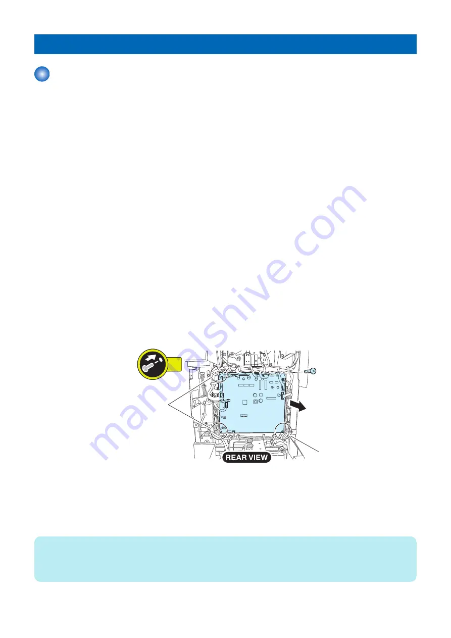
Removing the Folder Controller PCB
■ Actions before Replacing the Parts
● In case the host machine was able to store the adjustment values
1. Before replacing the Folder Controller PCB, store the adjustment values and the counter of the consumable parts
to the host machine from the service mode of the host machine.
Service Mode > SORTER > FUNCTION > FLD-BK-R
2. Turn OFF the main power switch to store the value.
● In cases the host machine was not able to store the adjustment values
1. Before replacing the Folder Controller PCB, output the service mode setting values P-PRINT.
Service Mode > COPIER > FUNCTION > MISC-P > P-PRINT
2. Turn OFF the main power switch
■ Preparation
1. Remove the rear upper cover.
“Removing the Rear Upper Cover” on page 64
■ Procedure
1. Disconnect all connectors and remove one screw and three locking supports [1] to remove the folder controller
PCB.
• All Connector
• 1 Screw
• 3 Locking Supports
1x
[1]
[1]
■ Actions after Replacing the Parts
1. Turn ON the main power switch.
2. If a message prompting the user to update the version appears, press [Update] to update automatically the version
of this equipment.
NOTE:
If [Skip] is selected, a message prompting the user to update the version will appear every time when the host machine is started.
It is possible to set not to display the message by the service mode (Level 2) shown below.
Service Mode_COPIER > OPTION > FNC-SW > VER-CHNG
4. Disassembly/Assembly
86
Summary of Contents for Paper Folding Unit-J1
Page 1: ...Revision 3 0 Paper Folding Unit J1 Service Manual ...
Page 9: ...Product Overview 1 Outline 4 Specifications 5 Names of Parts 9 ...
Page 18: ...Technical Explanation 2 Basic Configuration 13 Controls 25 Upgrading 55 ...
Page 62: ...Periodical Service 3 List of Work for Scheduled Servicing 57 ...
Page 73: ... Procedure 1 Remove the screws 2 Screws 2x 4 Disassembly Assembly 67 ...
Page 95: ...Adjustment 5 Overview 90 Major Adjustment 93 Action on parts replacement 105 ...
Page 155: ...13 Return the jam recovery map and close the front upper cover 6 Installation 149 ...
Page 158: ...APPENDICES Service Tools 153 General Circuit Diagram 154 ...


