


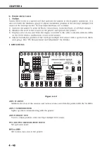


SW10 (Laser ON)
Emits laser from the laser diode.
SW11 (Enter)
Enters the data set by SW3 to SW9.
SW12 to SW14 (Display Select)
Set display mode.
SW15 (Reset)
Resets the printer driver tester.
3. Operation
a. Connecting to the printer
Note:
Before handling the printer driver tester, make sure to touch metallic parts of the print-
er to discharge electrical static as it may cause malfunctions or failures in the printer
and the tester.
Figure 4-8-3
1) Turn OFF the printer.
2) Connect the connector 1 of the tester to the envelope feeder connector in the printer. The seal
on the connector 1 should be facing up when connected to the envelope feeder connector.
Connect it to the duplexing unit connector on the back to check the envelope feeder opera-
tion. The seal on the connector 1 should be facing right (the left cover side) when connected
to the duplexing unit connector.
3) Turn ON the printer and operate the tester when the printer enters the standby mode.
Note:
Note that the connector of the tester fits into the connector on the wrong side. If the
LEDs on the tester do not light up when conducting the step 3, reconnect the connec-
tor the other way around.
4 - 49
CHAPTER 4
LED17
C o mm
u n ica
t i o n
SW15
Reset
CANON
INC
MADE
IN JAP
AN
RY9-0124
Cassette
Analog
Data
Reser
ved
Ser
vice
Error
Oper
ation
Error
Jam
Option
Sensor
Sensor/Switch
Reser
ved
0
0
0
0
0
0
1
1
0
0
1
1
1
1
1
1
0
1
0
1
0
1
0
1
SW1
SW1
SW1
Cassette
Pic
k-up
Envelope
Feeder
Pic
k-up
Paper
Feeder
Pic
k-up
MP
Tray
Pic
k-up
Reser
ved
Cassette
Pic
k-up
Oper
ation
Test
Density
Ajust.
Oper
ation
Mode
Select
SW1
0
1
0
SW2
1
0
0
All
Blac
k
All
white
Hor
izontal
lines
Vertical
lines
1
1
0
0
SW7
1
0
1
0
SW6
0
0
1
0
0
0
1
1
0
1
0
0
0
SW5
SW6
SW4
1
0
1
0
SW3
Nor
mal
F1
F5
F9
0
1
0
0
0
0
0
0
1
1
0
0
1
1
1
1
1
1
0
1
0
1
0
1
0
1
SW4
SW5
SW3
0
SW14
SW13
SW12
Displa
y Select
SW
10
S W
2
S W
1
PRINTER
DRIVER
TESTER
JC1
SW
1 1
2
1
0
test
cover
open
Full
delivery
2
delive
ry
1
TO P
pref
eed
M P
CASSETTE
SIZE
S W
9
S W
8
S W
7
S W
6
S W
5
S W
4
S W
3
Connector 1
Connector 2
Summary of Contents for LBP1760P
Page 8: ......
Page 10: ......
Page 12: ...This page intentionally left blank 1 2 CHAPTER 1...
Page 23: ...Figure 1 5 1 1 13 CHAPTER 1 100mm 1220mm 600mm 630mm...
Page 28: ...Figure 1 5 3 1 18 CHAPTER 1...
Page 34: ...This page intentionally left blank 1 24 CHAPTER 1...
Page 36: ......
Page 38: ......
Page 75: ...This page intentionally left blank 2 37 CHAPTER 2...
Page 80: ...Figure 2 5 3 2 42 CHAPTER 2...
Page 83: ...Figure 2 5 6 2 45 CHAPTER 2...
Page 85: ...This page intentionally left blank 2 47 CHAPTER 2...
Page 92: ......
Page 114: ......
Page 160: ......
Page 162: ......
Page 195: ...This page intentionally left blank 4 33 CHAPTER 4...
Page 199: ...This page intentionally left blank 4 37 CHAPTER 4...
Page 222: ...C Clutches Solenoids Figure 4 9 4 4 60 CHAPTER 4 SL102 CL101 SL101 SL701...
Page 224: ...D Motors Others Figure 4 9 6 4 62 CHAPTER 4 FM101 H901 M101 FM701 M702 M701...
Page 226: ...E PCBs Figure 4 9 7 4 64 CHAPTER 4...
Page 229: ...Figure 4 9 9 4 67 CHAPTER 4 J604 J602 J601 J104 J105 J72 J110 J603 J6 J7 J1 J8 J5 J4 J3 J2...
Page 232: ......
Page 234: ......
Page 270: ...COPYRIGHT C 1998 CANON INC CANON LBP 1760 REV 0 MAY 1998 PRINTED IN JAPAN IMPRIME AU JAPON...
Page 277: ......
Page 279: ......
Page 280: ......
Page 286: ......
Page 288: ......
Page 289: ......
Page 295: ......
Page 296: ......
Page 304: ......
Page 306: ...PRINTED IN JAPAN IMPRIME AU JAPON 0698AB0 50 CANON INC...
Page 310: ...COPYRIGHT C 1998 CANON INC CANON LBP 1760 REV 0 MAY 1998 PRINTED IN JAPAN IMPRIME AU JAPON iv...
Page 312: ...COPYRIGHT C 1998 CANON INC CANON LBP 1760 REV 0 MAY 1998 PRINTED IN JAPAN IMPRIME AU JAPON vi...
Page 313: ...COPYRIGHT C 1998 CANON INC CANON LBP 1760 REV 0 MAY 1998 PRINTED IN JAPAN IMPRIME AU JAPON vii...
Page 315: ......
Page 335: ......
Page 356: ......
Page 358: ......
Page 359: ......
Page 366: ......
Page 368: ......
Page 369: ......
Page 378: ......
Page 388: ......
Page 392: ......


