Canon iX7000 Series Service Manual Download Page 32

(4)  Carriage unit removal 


1) Remove the timing slit film. Be cautious to keep it free from any grease or damage. 

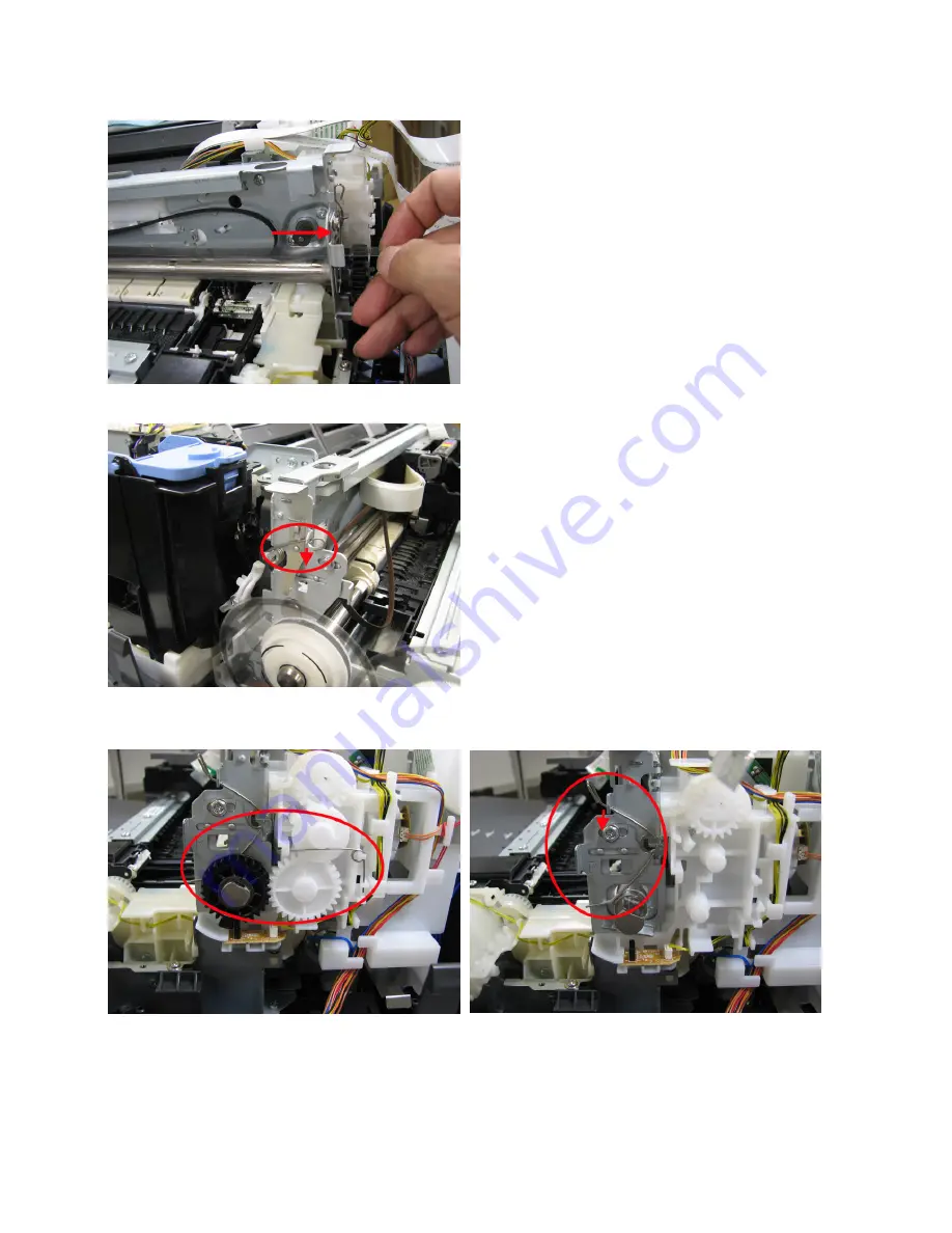
2) Remove the carriage shaft that fixes spring L. 

3) Disengage the gear spring, the carriage lift gears (two locations), and the carriage shaft cam, then 

remove the carriage shaft that fixes spring R. 

29 / 53

Summary of Contents for iX7000 Series

Page 1: ...raphical errors due to improvements or changes made to the product When changes are made to the contents of the manual Canon will release technical information when necessary When substantial changes are made to the contents of the manual Canon will issue a revised edition The following do not apply if they do not conform to the laws and regulations of the region where the manual or product is use...

Page 2: ...rors 2 3 Troubleshooting by Symptom 3 REPAIR 3 1 Major Replacement Parts 3 2 Part Replacement Procedures 1 External housing removal 2 Carriage unlocking 3 Printer unit removal 4 Carriage unit removal 5 ASF unit removal 6 Purge unit removal 7 Spur base unit and platen unit removal 4 ADJUSTMENT SETTINGS 4 1 User Mode 4 2 Service Mode 1 Service mode operation procedures 2 Service Tool functions 3 LF ...

Page 3: ...d printing uneven printing or non ejection of ink 3 Paper feed motor adjustment 4 Ink absorber counter setting 4 5 Verification After Repair 1 Standard inspection flow 2 Service test print 3 Ink absorber counter value print 5 PRINTER TRANSPORTATION TABLE OF CONTENTS ...

Page 4: ... in the ink absorber to the ink absorber counter Service Tool 1 Perform in the service mode 1 min Wetting liquid counter value setting EEPROM settings At logic board replacement At blade cleaner unit replacement To set the wetting liquid counter value Service Tool 1 Perform in the service mode 1 min Ink absorber replacement When the ink absorber becomes full To replace the ink absorber with a new ...

Page 5: ...f the carriage shaft other sliding parts and gears FLOIL KG 107A 1 min Ink system function check At logic board replacement At spur unit replacement At carriage unit replacement To maintain detection functionality for presence of the ink tanks and each ink tank position Service Tool 1 Perform in the service mode 1 min LF Eject correction At logic board replacement At paper feed roller replacement ...

Page 6: ...er does not feed properly When the front side of the paper is smeared To clean the pick up rollers of the rear tray and the cassette Computer printer driver 2 min Bottom plate cleaning When the back side of the paper is smeared To clean the platen ribs Feed the paper from the rear tray Printer buttons Computer printer driver 1 min Exterior cleaning When necessary To clean the printer exterior or t...

Page 7: ...slot Paper not properly set in the manual feed slot 7 Valve cam sensor Controls valve unit operation Reactor error 8 PE sensor Detects paper feeding and ejection No paper Paper jam 9 Purge cam sensor Controls purging operation PG cam sensor error 10 Pump roller sensor Detects the position of the pump roller Pump roller sensor error 11 Buffer tank sensor Detects Clear ink in the buffer tank No Clea...

Page 8: ...from the cassette from the front tray PF cam sensor error 22 Rear cover PE sensor Detects paper feeding and ejection at the rear cover No paper Paper jam in the rear cover 23 Reactor roller paper jam sensor Detects if paper winds around the reactor roller Paper jam 24 PF encoder sensor Detects rotation of the encoder during paper feeding from the cassette and controls its drive PF position error 2...

Page 9: ...Click on the image to enlarge it 6 53 ...

Page 10: ...7 53 ...

Page 11: ...1 5 Serial Number Location On the spur holder visible when the top cover is opened When the printer power is OFF When the printer power is ON 1 MAINTENANCE 8 53 ...

Page 12: ...t the rear tray is selected as the paper source The rear tray is only for photo papers and post cards Set the paper in the rear tray and press the Resume Cancel button ASF unit Pressure roller unit PE sensor Paper feed motor No paper in the cassette 1003 Confirm that the cassette is selected as the paper source The cassette is only for plain paper Set the paper in the cassette and press the Resume...

Page 13: ...m the cassette Rear tray unit Rear tray holder R unit Paper jam in the rear cover 1307 Open the rear cover remove the jammed paper or foreign material causing a paper jam paper remainings clips pens etc then press the Resume Cancel button The error is indicated at paper jam in the rear cover during paper feeding from the cassette or during manual paper feeding from the front tray ASF unit 4 times ...

Page 14: ...ont tray though paper is supposed to be set in the manual feed slot ASF unit Bottom case unit Cassette 7 times Multiple ink tanks of the same color installed 1487 U071 Replace the wrong ink tank s with the correct one s Ink tank Logic board Ink tank in a wrong position 1680 U072 Install the ink tank s in the correct position 8 times Warning The ink absorber becomes almost full 1700 Replace the ink...

Page 15: ... does not occur Carriage unit Logic board Smearing on the paper feed rollers 1870 1 Perform Sheet cleaning using the Cleaning Sheet The error is indicated at every 5 000 pages of paper feeding from the cassette 12 times Ink tank replaced during printing 1350 1 If ink runs out and the empty ink tank is replaced during printing ink agitation is performed after the ink tank replacement then printing ...

Page 16: ...nk and press the Resume Cancel button Unless the Clear ink tank is replaced with a new one the error will not be cleared only by pressing the Resume Cancel button If the error persists even after replacement of the Clear ink tank press and hold the Resume Cancel button in the user mode until the Alarm lamp blinks 9 times release the button then remove and re install the Clear ink tank Clear ink ta...

Page 17: ...nk tank with a new one This error is indicated when the applicable ink tank has been removed before the error occurrence Printing with an empty ink tank can damage the printer To continue printing without replacing the ink tank s press the Resume Cancel button for 5 sec or longer to disable the function to detect the remaining ink amount After the operation it is recorded in the printer that the f...

Page 18: ...hat obstructs the carriage movement remove foreign material 3 Ink tank conditions re set the ink tanks 4 Cable connection 5 Part replacement Timing slit film Carriage unit Logic board Carriage motor 3 times Line feed error 6000 An error occurred in the LF encoder signal 1 Smearing or scratches on the LF slit disk film clean the LF slit disk film 2 Foreign material or paper debris in the LF drive r...

Page 19: ...rint head temperature rise error 5200 The print head temperature exceeded the specified value 1 Print head condition 2 Cable connection 3 Part replacement Print head Logic board Reactor error B300 A hardware error occurred in supplying Clear ink 1 Part replacement Valve unit Sheet feed unit Logic board 9 times EEPROM error 6800 6801 A problem occurred in reading from or writing to the EEPROM 1 Par...

Page 20: ...it disk film clean the EJ slit disk film 2 Foreign material or paper debris in the paper path remove foreign material 3 Cable connection 4 Part replacement EJ slit disk film LF EJ timing sensor unit Platen unit Logic board Paper feed motor 19 times Ink tank position sensor error 6502 None of the ink tank position is detected 1 Ink tank position confirm the ink tank position 2 Re set or replacement...

Page 21: ... board Pressure roller unit Platen unit Unsatisfactory print quality No printing or no color ejected Faint printing or white lines on printouts Uneven printing Improper color hue 1 Confirm the ink tank conditions Confirmation of the air through of an ink tank Re setting of an ink tank 2 Remove foreign material from the purge unit caps if any 3 Perform cleaning or deep cleaning of the print head 4 ...

Page 22: ... from smearing or scratches Cleaning of the timing slit film 2 Replace the following item s Timing slit film Carriage unit Logic board Graphic or text is enlarged on printouts in the paper feed direction 1 Confirm that the LF EJ slit film is free from smearing or scratches Cleaning of the LF EJ slit film 2 Replace the following item s LF EJ slit film LF EJ timing sensor unit Platen unit Logic boar...

Page 23: ...Mode for details 7 Perform print head alignment in the user mode EEPROM information print Service test print 2 Printing via USB connection Absorber kit 15 1 External housing 2 Printer unit 3 Absorber kit After replacement 1 Reset the ink absorber counter See 4 2 Service Mode for details Ink absorber counter value print After the ink absorber counter is reset the counter value is printed automatica...

Page 24: ...n After Repair for details EEPROM information print Service test print Purge unit 15 1 External housing 2 Printer unit 3 Blade cleaner unit 4 Purge unit After replacement 1 Confirm the purging operation and the printer operation See 4 5 Verification After Repair for details Service test print Feed roller ass y 35 1 External housing 2 Printer unit 3 Spur base unit 4 Platen unit 5 Sheet feed unit 6 ...

Page 25: ...units from soiled with ink Protect the housing from scratches Exercise caution with the screws as follows i The screws of the paper feed motor may be loosened only at replacement of the paper feed motor unit DO NOT loosen them in other cases See 4 4 Special Notes on Servicing 3 Paper feed motor adjustment for details Do not bend the film Print head 1 After replacement 1 Perform print head alignmen...

Page 26: ...from static electricity in repair servicing especially for the logic board and panel board 1 External housing removal iX7000 3 REPAIR TABLE OF CONTENTS 1 Remove the cassette 2 Remove the LAN connector cap if attached 3 Remove the side cover L Open the Clear ink tank cover and release 3 tabs 23 53 ...

Page 27: ...lease 2 tabs 5 Remove the panel cover Remove one screw While pulling the top and bottom edges of the panel outward slide the panel cover toward you to release the two tabs on the front of the printer Disconnect one connector 24 53 ...

Page 28: ... the front cover Remove 2 screws 7 Remove the main case Remove 2 screws from the front and 2 screws from the back total of 4 screws Disconnect the connector Release 2 tabs each on the left and right sides 25 53 ...

Page 29: ...3 Printer unit removal Rotate the gear of the purge unit to unlock the carriage and slide the carriage to the left to the opposite of the home position 1 Remove the top cover 2 screws and the logic board cover 3 screws 26 53 ...

Page 30: ...he connectors from the logic board and release the cables from the logic board holder 3 Remove 3 screws and the logic board holder 4 Release the cables except the power cable the blue cable from the bottom case 27 53 ...

Page 31: ...5 Remove 5 screws that fix the printer unit to the bottom case and 1 screw from the front tray sensor then separate the printer unit from the bottom case 28 53 ...

Page 32: ...lm Be cautious to keep it free from any grease or damage 2 Remove the carriage shaft that fixes spring L 3 Disengage the gear spring the carriage lift gears two locations and the carriage shaft cam then remove the carriage shaft that fixes spring R 29 53 ...

Page 33: ...e carriage shaft 5 Release the cables at the back of the chassis and remove the carriage cable holder and carriage belt Then remove the carriage unit 6 Remove the carriage shaft and the cam on the left side 30 53 ...

Page 34: ...tank holder Disconnect all the connectors from the PF relay L board Remove 2 screws and release the tube 2 Remove the cable holder on the right side Disconnect one connector and release the cables from the cable holder then remove 3 screws 31 53 ...

Page 35: ...3 Release the cables from the cable holder 4 Remove the valve unit Disconnect the tube Remove 2 screws Disconnect the connector 32 53 ...

Page 36: ...5 Remove the Clear ink tank holder 2 screws 6 Remove the cable holder L and the valve unit base 5 screws and one connector 7 Disengage the gear that connects to the carriage lift mechanism 33 53 ...

Page 37: ...8 Remove the ASF unit 5 screws 34 53 ...

Page 38: ... 6 Purge unit removal 1 Disconnect the tube 2 Remove 3 screws 3 Disconnect the carriage lift sensor connector and release the cables from the holder 35 53 ...

Page 39: ...push the purge unit to release it 6 Lift the carriage shaft and pull the purge unit to remove from the chassis 7 Separate the blade cleaner unit from the purge unit 2 screws Note that the blade cleaner unit alone can be removed only by removing the external housing 36 53 ...

Page 40: ...e cables from the cable holder and disconnect the connector 2 Remove the eject timing slit disk 3 Remove the spur base unit From the top of the spur base unit remove 2 screws at the left and right ends Slide the spur base unit toward you to remove it 37 53 ...

Page 41: ...4 Remove the cable holder 5 Remove the platen unit Rotate the bushing of the eject roller to disengage the roller and pull the platen unit to remove it 3 2 Part Replacement Procedures 38 53 ...

Page 42: ...ce tab 2 times Set a sheet of plain paper A4 or Letter in the cassette No paper feeding from the rear tray Print head deep cleaning Perform from the printer driver Maintenance tab If print head manual cleaning is not effective perform this cleaning Since the deep cleaning consumes more ink than regular cleaning it is recommended to perform deep cleaning only when necessary Automatic print head ali...

Page 43: ...ance automatically is not selected in Custom Settings periodic ink agitation is not performed automatically Manually perform ink agitation once a week Periodic paper feed roller cleaning Perform from the printer driver Maintenance tab Sheet Cleaning When You need to execute sheet cleaning because the predetermined print count has been reached is displayed perform Sheet cleaning using the Cleaning ...

Page 44: ...ume Cancel buttons Each time the Resume Cancel button is pressed the Alarm and Power LEDs light alternately Alarm in orange and Power in green starting with Alarm LED iv When the Power LED lights in green the printer is ready for the service mode operation 2 Start the Service Tool on the connected computer i When a button is clicked in the Service Tool dialog box that function is performed During ...

Page 45: ...version USB serial number Process inspection information Ink system function check result Ink absorber counter value ink amount in the ink absorber Barcode model name destination printer serial number 2 EEPROM EEPROM information print The dialog box opens to select the paper source Select Rear tray or Cassette and click OK EEPROM information print items Model name ROM version Ink absorber counter ...

Page 46: ...n The following items are NOT initialized and the shipment arrival flag is not on USB serial number Destination settings Record of ink absorber counter resetting and setting Record of repair at the production site Production site E MIP correction value and enabling of it Record of disabling the function to detect the remaining ink amount Ink absorber counter value ink amount in the ink absorber We...

Page 47: ...No in which streaks or lines are the least noticeable for the LF check pattern and the Eject check pattern respectively LF Pattern No 0 to 4 Eject Pattern No 0 to 4 4 Select and set the correction values In the LF EJECT Correction section of the Service Tool select the Pattern No from 0 to 4 determined in step 3 for LF and EJECT respectively and click Set 5 The selected LF and Eject correction val...

Page 48: ... logic board is replaced in servicing When the blade cleaner unit is replaced 1 After replacement of the blade cleaner unit the wetting liquid counter value should be reset in the service mode using the Service Tool In the Wetting Liquid Counter section of the Service Tool select 0 zero from the Counter Value pull down menu and click Set 2 Print EEPROM information to confirm that the value is set ...

Page 49: ...st plate R Carriage shaft cam R sliding portion KG107A 18 to 36 2 1 5 Chassis Carriage shaft sliding portion KG107A 9 to 18 1 1 6 Chassis PR lift shaft sliding portion KG107A 13 5 to 27 1 5 x 4 7 7 Carriage shaft spring L Carriage shaft sliding portion KG107A 9 to 18 1 1 8 Carriage shaft The entire surface where the carriage slides KG107A 280 to 580 9 CL input gear CL gear base sliding portion KG1...

Page 50: ...47 53 ...

Page 51: ...curely connected 2 Replace the Clear ink tank 3 Replace the valve unit 2 For smeared printing uneven printing or non ejection of ink When smeared printing uneven printing or non ejection of ink occurs print the nozzle check pattern to determine whether the print head is faulty or not Procedures 0 Using the tool print head confirm that the test printer to be used to examine the print head in questi...

Page 52: ...oard check the ink absorber counter value and register it to the replaced new logic board The value can be set in 10 increments In addition according to the ink absorber counter value replace the ink absorber ink absorber kit When the ink absorber is replaced reset the applicable ink absorber counter to 0 How to check the ink absorber value and the way to set the ink absorber counter See 4 2 Servi...

Page 53: ...ce Tool version 1 05 or later Communication with a connected computer Check point Via USB connection to the computer printing from the computer must be performed properly paper feeding from the rear tray and from the cassette respectively Additional verification to be made For repair of a specific problem confirm the applicable specific function in the user mode Wired LAN Manual paper feeding Dupl...

Page 54: ... 2 Service test print Service test print sample Print on A3 or LDR sized paper 51 53 ...

Page 55: ... 3 Ink absorber counter value print Print sample 4 5 Verification Items 52 53 ...

Page 56: ...attach the protective cap used when the packing was opened to the print head to protect the print head face from damage due to shocks If the packing material that fixed the carriage from the factory is still available re use it to fix the carriage to prevent the carriage unlocked during transportation iX7000 TABLE OF CONTENTS 1 If the print head is removed from the printer and left alone by itself...

Reviews: