4-23
4
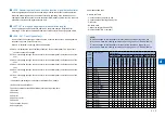
Note:
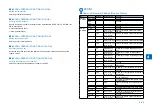
Be sure to enter the value on service label when executing RAM clear of the reader
controller PCB/ replacing the reader controller PCB.
If changing the setting value of this item, be sure to Note the changed value on the
reader's service label.l.
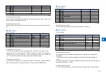
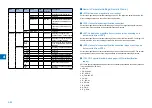
(#SCAN> READER> ADJUST> CCD> W-PLT-X)
White label data entry with standard white plate.
(#SCAN> READER> ADJUST> CCD> W-PLT-Y)
White label data (Y) entry with standard white plate.
(#SCAN> READER> ADJUST> CCD> W-PLT-Z)
White label data (Z) entry with standard white plate.
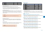
Execute this mode only when necessary. Do not execute it when unnecessary.
Note:
Be sure to enter the value on service label when replacing the CCD unit.
Be sure to enter the numeric value on copyboard glass when replacing the copyboard
glass.
If changing the setting value of this item, be sure to Note the changed value on the
service label.
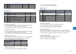
(#SCAN> READER> ADJUST> CCD> SH-TRGT)
Shading target value of the standard white plate (backup).
This item must not be normally used.
(#SCAN> READER> ADJUST> CCD> DFTAR-R)
Shading target value (RED) entry when using DF (normal document scanning position).
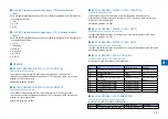
(#SCAN> READER> ADJUST> CCD> DFTAR-G)
Shading target value (GREEN) entry when using DF (normal document scanning position).
(#SCAN> READER> ADJUST> CCD> DFTAR-B)
Shading target value (BLUE) entry when using DF (normal document scanning position).
This item must not be normally used.
●
●
●
●
●
●
●
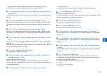
(#SCAN> READER> ADJUST> CCD> DFTAR-K)
Black shading target value when using DF.
This item must not be normally used.
In case of image fault (due to chart soil, etc) after executing: SCAN > READER > FUNCTION
> CCD > DFWLVL1/ DF-WLVL2; enter the factory measurement value using this mode.
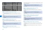
(#SCAN> READER> ADJUST> PASCAL> OFST-P-K)
Density adjustment at test print scanning.
Execute offset adjustment for test print scanning signal in PASCAL control at auto gradation
correction (full correction)
(#SCAN> READER> FUNCTION> INSTALL> STRD-POS)
Auto adjustment of CCD reading position in stream reading.
When installing the DF, or removing the ADF and reinstalling it.
(#SCAN> READER> FUNCTION> CCD> CCD-ADJ)
Gain adjustment of analog processor block (on CCD PCB).
When installing the DF, or removing the ADF and reinstalling it.
The gain of LED of CIS is corrected to set the CIS parameter automatically. (AGC adjustment)
Execute this after replacing the CIS unit.
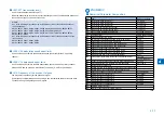
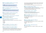
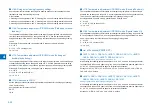
(#SCAN> READER> FUNCTION> CCD> DF-WLVL1)
ADF white level adjustment (platen board cover scan/stream reading scan).
(#SCAN> READER> FUNCTION> CCD> DF-WLVL2)
ADF white level adjustment (platen board cover scan/stream reading scan).
1) Place a paper that users normally use on the copyboard glass and execute the following
item; SCAN > READER > FUNCTION > CCD > DFWLVL1/ DF-WLVL2
: Read the white level in BOOK mode. (Check the transparency of the glass for BOOK mode.)
2) Set a paper that users normally use and execute the following item;
SCAN > READER > FUNCTION > CCD > DFWLVL1/ DF-WLVL2
: Read the white level in DF mode (stream reading). (Check the transparency of the glass for
stream reading.) (Read the both sides of chart.) Reading the face: Calculate DFTAR-R
Note:
Be sure to execute these two items (DF-WLVL1/DF-WLVL2) simultaneously.
●
●
●
●
●
●
Summary of Contents for IMAGERUNNER 2530
Page 9: ...1 1 Periodical Service Consumable Parts and Cleaning Parts ...
Page 13: ...1 5 1 Cleaning Parts Fixing guide Transfer guide F 1 2 F 1 2 ...
Page 14: ...2 2 Adjustment Overview Adjustment when replacing parts image position adjustment ...
Page 20: ...3 3 Error Code Overview Error Code Jam Code Alarm Code ...
Page 34: ...4 4 Service Mode Overview Details of Service Mode ...
Page 85: ...5 5 Parts Replacement and Cleaning List of Parts ...
Page 98: ...6 6 Product Overview Specifications Product lineups Basic Configuration ...
Page 106: ...7 7 Version Upgrading Upgrading Targets and Procedure ...

