


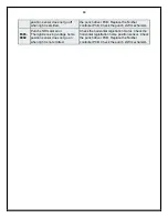


11
is not detected for 100 msec.)
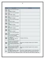
E064-
0005
The voltage of the power supply is faulty (high-
voltage error).
While output is being generated, the AD value of the
transfer output voltage is 0 (DEC) for 100 msec 2
times in sequence. (However, after output, it is not
detected for 100 msec.)
Replace the high-voltage power
supply. Replace the DC
controller PCB.
E100-
0001
The BD interval is outside a specific range.
After the machine has become ready for image
formation (i.e., the scanner motor is ready for
operation, and the laser has been turned on), an
error has occurred 50 times or more (BD error).
Replace the laser unit. Replace
the DC controller PCB. Check
the wiring.
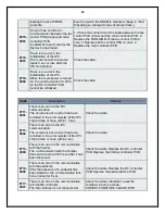
E110-
0001
The scanner motor is faulty.
The scanner motor speed lock signal does not
indicate a locked state a specific period of time after
the scanner motor has been started.
Replace the laser unit. Replace
the DC controller PCB. Check
the wiring.
E110-
0002
The scanner motor is faulty.
The speed lock signal indicates a deviation 10 times
in sequence at intervals of 10 msec after the signal
has indicated a locked state.
Replace the laser unit. Replace
the DC controller PCB. Check
the wiring.
E110-
0003
The scanner motor is faulty.
With the image clock switched over, the scanner
motor speed lock signal does not indicate a locked
state 6.5 sec after a switchover is made from low to
normal speed or 8 sec after a switchover is made
from normal to low speed
Replace the laser unit. Replace
the DC controller PCB. Check
the wiring.
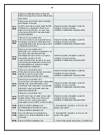
E191-
0000
There is an error in the communication with the high-
voltage power supply
The data transmission/reception does not end
normally 500 msec after the most recent
transmission/reception of data ended normally.
Replace the high-voltage power
supply. Replace the DC
controller PCB.
E202-
0001
There is an error in the detection of the CIS home
position.
The attempt to detect the home position fails when
the CIS is moved forward
Disconnect and then connect the
harness connector. Replace the
following as necessary: scanner
home position sensor, scanner
motor, reader controller PCB.
E202-
0002
There is an error in the detection of the CIS home
position.
The attempt to detect the home position fails when
the CIS is moved back.
Disconnect and then connect the
harness connector. Replace the
following as necessary: scanner
home position sensor, scanner
motor, reader controller PCB.
E225-
0001
The light intensity of the CIS is faulty.
During shading operation, the intensity is below a
specific level.
Disconnect and then connect the
flexible cable. Replace the
following as necessary: flexible
cable, CIS, reader controller
PCB.