


Chapter 2
2-21
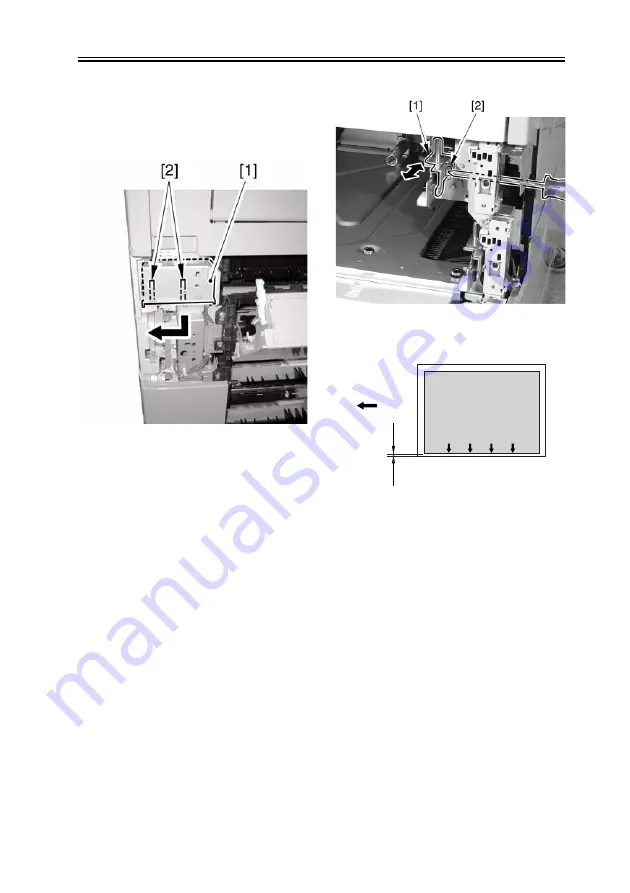
6) Remove the 2 claws [2], and detach the
grip (right front) [1] in the direction of
the arrow.
F-2-46
7) Loosen the fixing screw [2] of the
adjusting plate [1].
8) While referring to the index you
checked in step 5), move the adjusting
plate back and forth. Moving the
adjusting plate toward the rear of the
machine will increase the left margin L1
of the image.
F-2-47
F-2-48
[1]Paper feed direction
9) Tighten the fixing screw.
10) Fit the cassette 1 back in.
11) Make a copy, and check to be sure that
the left margin of the image on paper
picked up from the cassette 1 is 2.5 +/-
1.5 mm.
12) Fit the grip (right front) back in.
13) Attach the right cover of the machine.
*Adjusting the Cassette 2
6) Loosen the fixing screw [2] of the
adjusting plate [1].
7) While referring to the index you
checked in step 5), move the adjusting
image
L1
[1]
Summary of Contents for imageRUNNER 2270
Page 18: ...Chapter 1 Introduction ...
Page 21: ...Chapter 1 1 2 iR 3570 iR 4570 F 1 1 6 2a 1a 3a 6a 4a 5a 1 3 4 2 5 ...
Page 42: ...Chapter 1 1 23 F 1 13 ON OFF ...
Page 64: ...Chapter 1 1 45 F 1 15 F 1 16 ...
Page 77: ...Chapter 2 Installation ...
Page 129: ...Chapter 3 Basic Operation ...
Page 135: ...Chapter 4 Main Controller ...
Page 164: ...Chapter 5 Original Exposure System ...
Page 211: ...Chapter 6 Laser Exposure ...
Page 227: ...Chapter 7 Image Formation ...
Page 281: ...Chapter 8 Pickup Feeding System ...
Page 397: ...Chapter 9 Fixing System ...
Page 426: ...Chapter 9 9 28 F 9 55 3 Disconnect the connector 1 and detach the fixing film sensor 2 ...
Page 427: ...Chapter 10 External and Controls ...
Page 485: ...Chapter 11 MEAP ...
Page 491: ...Chapter 12 Maintenance and Inspection ...
Page 497: ...Chapter 12 12 5 F 12 1 1 2 3 4 5 6 7 8 8 9 9 9 9 11 10 12 12 13 13 ...
Page 507: ...Chapter 12 12 15 3 Remove the waste toner box 1 F 12 7 4 Open the right door 1 F 12 8 ...
Page 521: ...Chapter 12 12 29 2 Disconnect the 3 connectors 1 F 12 35 3 Remove the 4 screws 1 F 12 36 ...
Page 530: ...Chapter 13 Standards and Adjustments ...
Page 557: ...Chapter 14 Correcting Faulty Images ...
Page 564: ...Chapter 14 14 6 Image Sample F 14 1 ...
Page 566: ...Chapter 14 14 8 F 14 2 ...
Page 568: ...Chapter 14 14 10 F 14 3 ...
Page 570: ...Chapter 14 14 12 F 14 4 ...
Page 572: ...Chapter 14 14 14 Image Sample F 14 5 ...
Page 574: ...Chapter 14 14 16 F 14 6 ...
Page 576: ...Chapter 14 14 18 F 14 7 ...
Page 578: ...Chapter 14 14 20 F 14 8 ...
Page 580: ...Chapter 14 14 22 F 14 9 ...
Page 586: ...Chapter 14 14 28 F 14 12 M4 M1 M12 M3 M2 M6 M7 M5 M10 ...
Page 605: ...Chapter 15 Self Diagnosis ...
Page 684: ...Chapter 16 Service Mode ...
Page 808: ...Chapter 17 Service Tools ...
Page 813: ...Appendix ...
Page 830: ......
Page 837: ...Chapter 1 Specification ...
Page 842: ...Chapter 2 Functions ...
Page 859: ...Chapter 3 Installation ...
Page 871: ...Chapter 4 Parts Replacement Procedure ...
Page 902: ...Chapter 5 Maintenance ...
Page 908: ......
Page 914: ...Chapter 1 Installation ...
Page 920: ......
Page 927: ...Chapter 1 Specifications ...
Page 934: ...Chapter 2 Functions ...
Page 946: ...Chapter 3 Installation ...
Page 958: ...Chapter 3 3 11 17 Close the upper front cover 1 F 3 32 ...
Page 960: ...Chapter 4 Parts Replacement Procedure ...
Page 965: ...Chapter 4 4 4 F 4 11 6 Detach the extension delivery kit 1 from the host machine ...
Page 987: ...Chapter 5 Maintenance ...
Page 992: ...Appendix ...
Page 994: ......


