


Chapter 2
2-8
2.2
Unpacking and
Installation
2.2.1
Unpacking and
Removing the
Packaging
Materials
0006-6724
1) Unpack and remove the plastic bags.
- When installing a pedestal to the copier at
the same time, unpack it in the same
way.
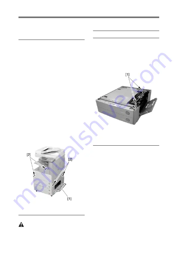
2) When installing the copier on the 2-
cassette Pedestal-Y2, open the right
door [1] of the pedestal.
3) Hold the recesses [2] of the copier with
4 or more people, and place it on the
pedestal.
F-2-8
The maximum weight of the copier is
approx. 80kg (including the DADF), so
be sure to lift it with 4 or more people.
Memo: When placing the copier on the
cassette pedestal, be sure to align the two
positioning pins [1] to the holes on the base
plate of the copier.
F-2-9
4) Close the right door of the pedestal (in
the case of the 2-cassette Pedestal-Y2).
5) Remove the packaging tapes and
materials from each unit.
- Front door
- Right door
- Manual feeder unit
- Cassettes 1 and 2
- Inside the cassettes 1 and 2
- DADF (In the case of the model with a
DADF)
- Platen glass
6) When installing the copier to the 2-
cassette Pedestal-Y2, follow the
Summary of Contents for imageRUNNER 2270
Page 18: ...Chapter 1 Introduction ...
Page 21: ...Chapter 1 1 2 iR 3570 iR 4570 F 1 1 6 2a 1a 3a 6a 4a 5a 1 3 4 2 5 ...
Page 42: ...Chapter 1 1 23 F 1 13 ON OFF ...
Page 64: ...Chapter 1 1 45 F 1 15 F 1 16 ...
Page 77: ...Chapter 2 Installation ...
Page 129: ...Chapter 3 Basic Operation ...
Page 135: ...Chapter 4 Main Controller ...
Page 164: ...Chapter 5 Original Exposure System ...
Page 211: ...Chapter 6 Laser Exposure ...
Page 227: ...Chapter 7 Image Formation ...
Page 281: ...Chapter 8 Pickup Feeding System ...
Page 397: ...Chapter 9 Fixing System ...
Page 426: ...Chapter 9 9 28 F 9 55 3 Disconnect the connector 1 and detach the fixing film sensor 2 ...
Page 427: ...Chapter 10 External and Controls ...
Page 485: ...Chapter 11 MEAP ...
Page 491: ...Chapter 12 Maintenance and Inspection ...
Page 497: ...Chapter 12 12 5 F 12 1 1 2 3 4 5 6 7 8 8 9 9 9 9 11 10 12 12 13 13 ...
Page 507: ...Chapter 12 12 15 3 Remove the waste toner box 1 F 12 7 4 Open the right door 1 F 12 8 ...
Page 521: ...Chapter 12 12 29 2 Disconnect the 3 connectors 1 F 12 35 3 Remove the 4 screws 1 F 12 36 ...
Page 530: ...Chapter 13 Standards and Adjustments ...
Page 557: ...Chapter 14 Correcting Faulty Images ...
Page 564: ...Chapter 14 14 6 Image Sample F 14 1 ...
Page 566: ...Chapter 14 14 8 F 14 2 ...
Page 568: ...Chapter 14 14 10 F 14 3 ...
Page 570: ...Chapter 14 14 12 F 14 4 ...
Page 572: ...Chapter 14 14 14 Image Sample F 14 5 ...
Page 574: ...Chapter 14 14 16 F 14 6 ...
Page 576: ...Chapter 14 14 18 F 14 7 ...
Page 578: ...Chapter 14 14 20 F 14 8 ...
Page 580: ...Chapter 14 14 22 F 14 9 ...
Page 586: ...Chapter 14 14 28 F 14 12 M4 M1 M12 M3 M2 M6 M7 M5 M10 ...
Page 605: ...Chapter 15 Self Diagnosis ...
Page 684: ...Chapter 16 Service Mode ...
Page 808: ...Chapter 17 Service Tools ...
Page 813: ...Appendix ...
Page 830: ......
Page 837: ...Chapter 1 Specification ...
Page 842: ...Chapter 2 Functions ...
Page 859: ...Chapter 3 Installation ...
Page 871: ...Chapter 4 Parts Replacement Procedure ...
Page 902: ...Chapter 5 Maintenance ...
Page 908: ......
Page 914: ...Chapter 1 Installation ...
Page 920: ......
Page 927: ...Chapter 1 Specifications ...
Page 934: ...Chapter 2 Functions ...
Page 946: ...Chapter 3 Installation ...
Page 958: ...Chapter 3 3 11 17 Close the upper front cover 1 F 3 32 ...
Page 960: ...Chapter 4 Parts Replacement Procedure ...
Page 965: ...Chapter 4 4 4 F 4 11 6 Detach the extension delivery kit 1 from the host machine ...
Page 987: ...Chapter 5 Maintenance ...
Page 992: ...Appendix ...
Page 994: ......


