Chapter 2
2-10
2.3.2 Ink Passage
2.3.2.1 Ink Passage
2.3.2.1.1 Overview of Ink Passage
0012-6328
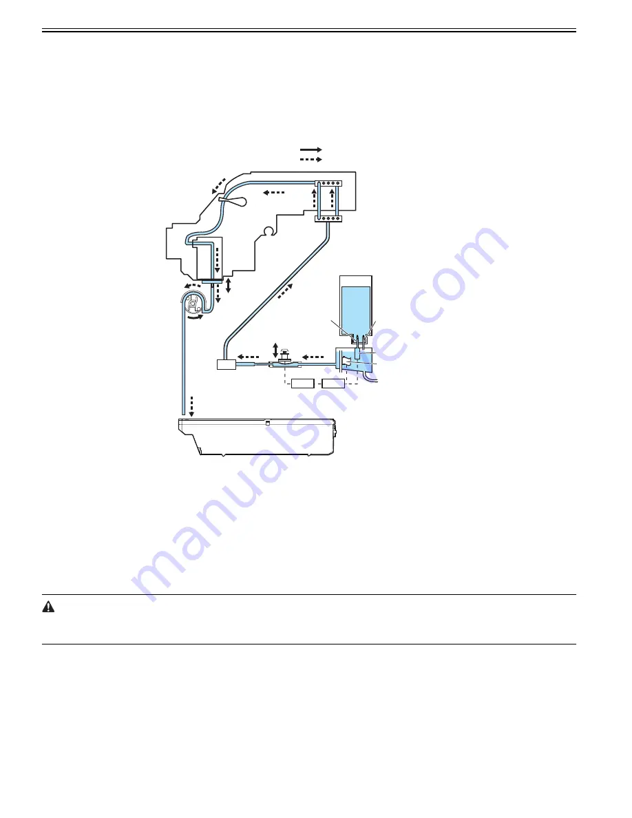
The ink passage comprises ink tanks, a printheads, caps, a maintenance jet tray, a maintenance cartridge, ink tubes interconnecting the mechanical components of
the printer, and a suction pump that is driven to suck inks. It supplies, circulates, sucks and otherwise handles inks.
The ink passage (per color) is schematically shown below, along with the ink flow.
F-2-8
a) Supplying inks from the ink tanks to the ink supply valve assembly
The ink tanks each contain ink to feed the printhead.
Head differences allow the inks to flow from the ink tanks to the subtanks first, then to the ink supply valves.
Air is discharged through the air passage of the subtanks to keep the internal pressure of the ink tanks constant.
b) Supplying inks from the ink supply valves to the printhead
The ink stored in an ink tank flows to the printhead when the suction pipe is driven with the ink supply valve opened and the head capped.
c) Supplying inks while printing
The ink supply valves are kept open while printing, so that ink is constantly flowing to the printhead under the negative pressure of the nozzle assembly which is
caused by the discharging inks.
Furthermore, waste inks sucked in the cleaning operation and inks from the maintenance jet tray flow into the maintenance cartridge.
Opening all the ink passages (by opening both the ink supply valve and the printhead fixer lever with an ink tank yet to be installed) while an ink tube is being filled
with ink could cause the ink in the ink tube to flow backwards due to a head pressure difference, causing leakage through the hollow needle in the ink tank.
As a precaution, never open all the ink passages at the same time while the ink tubes are being filled with inks.
d) Ink agitating
Ink will be agitated to prevent the element of the pigment ink from subsiding in the ink tank and the sub-tank.
The valve motor drive is transmitted to the agitation cam, the agitation fin in the sub-tank rotates and ink in the sub-tank will be agitated. In addition, ink flows
backward by moving the piston under the needle(ink supply) up and down in the ink tank, and ink in the ink tank will be agitated.
Maintenance cartridge
Ink tank
Ink supply vavle
Joint
Joint
Carriage unit
Printhead
Cap
Suction pump
Mechanical Drive Unit
Ink or air flow
Subtank
Agitation fin
Needle(ink supply)
Piston
Needle(air passage)
Valve
motor
Agitation
cam
Summary of Contents for imagePROGRAF iPF8400
Page 2: ......
Page 6: ......
Page 11: ...Chapter 1 PRODUCT DESCRIPTION ...
Page 12: ......
Page 14: ......
Page 63: ...Chapter 2 TECHNICAL REFERENCE ...
Page 64: ......
Page 106: ......
Page 107: ...Chapter 3 INSTALLATION ...
Page 108: ......
Page 110: ......
Page 123: ...Chapter 3 3 13 F 3 22 6 FAN UNIT A ...
Page 125: ...Chapter 3 3 15 ...
Page 126: ......
Page 127: ...Chapter 4 DISASSEMBLY REASSEMBLY ...
Page 128: ......
Page 130: ......
Page 167: ...Chapter 4 4 37 ...
Page 168: ......
Page 169: ...Chapter 5 MAINTENANCE ...
Page 170: ......
Page 172: ......
Page 177: ...Chapter 6 TROUBLESHOOTING ...
Page 178: ......
Page 180: ......
Page 214: ......
Page 215: ...Chapter 7 SERVICE MODE ...
Page 216: ......
Page 218: ......
Page 273: ...Chapter 7 7 55 ...
Page 274: ......
Page 275: ...Chapter 8 ERROR CODE ...
Page 276: ......
Page 278: ......
Page 296: ......
Page 297: ...Appendix ...
Page 298: ......
Page 307: ...Sep 14 2012 ...
Page 308: ......


