CHAPTER 2 FUNCTIONS & OPERATION
1) Feed path
The feed path of this machine is a
straight path tilting at an angle of
approximately 40 degrees.
For details on the arrangement of the
rollers, sensors, and other components,
refer to the cross sectional diagram of
the feed system given earlier. There is no
pickup roller.
Documents placed in the inlet are ejected
to the eject tray. However, the document
can be output even when the eject tray is
closed. When feeding cards, orient the
card sideways.
2) Drive
The feed motor drives the feed roller and
the retard roller, and the main motor
drives the registration roller and the eject
roller. The scanning condition determines
each drive speed.
Furthermore, the document stopper and
pressure roller are moved up and down
by rotating the main motor backwards.
3) Feed
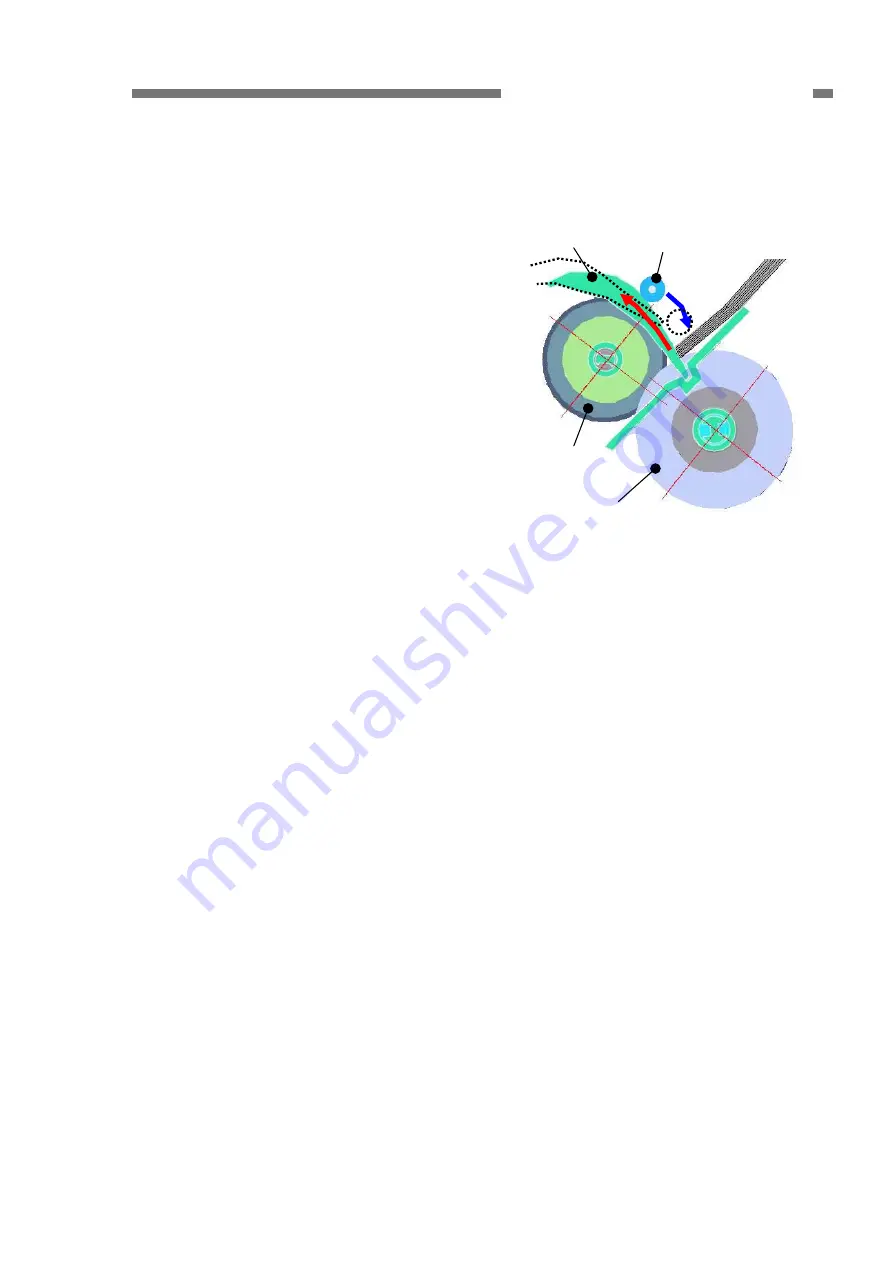
The following shows a cross-sectional
diagram of the pickup area before
starting the feed. The document stopper
is in the lowered position.
When a document is placed in the inlet,
the edge of the document lines up at the
document stopper. When a scan is
started, the pressure roller moves down
and then the document stopper moves
up and the document begins to feed.
Documents feed from the lower side of
the placed document.
Misfeeds and double feeds have been
reduced by installing a document stopper
and pressure roller, and increasing the
diameter of the feed roller.
Document
stopper
Pressure roller
Document
Retard roller
Feed roller
Figure 2-302
4) Separation
Separation of the documents is
performed by the retard roller.
Since the torque limiter is built in the
retard roller, when the outside pressure
on the roller exceeds the specified value
into the feed direction, the roller begins to
rotate in the same direction.
As shown in Figure 2-303-a, when
overlapped documents enter into the
clearance between the feed roller and
the retard roller, the document in contact
with the feed roller is fed in the feed
direction, and the retard roller rotates in
the opposite direction so that the
document in contact with the retard roller
is not pushed in.
As shown in Figure 2-303-b, once a
single document remains, the feed roller
and the document add torque on the
retard roller. When this torque exceeds
the retard roller torque, the retard roller
rotates in the direction to feed the
document due to the torque limiter.
COPYRIGHT
©
CANON ELECTRONICS INC. 2011 CANON DR-M160 FIRST EDITION
2-9


