background image

Setting Up

12

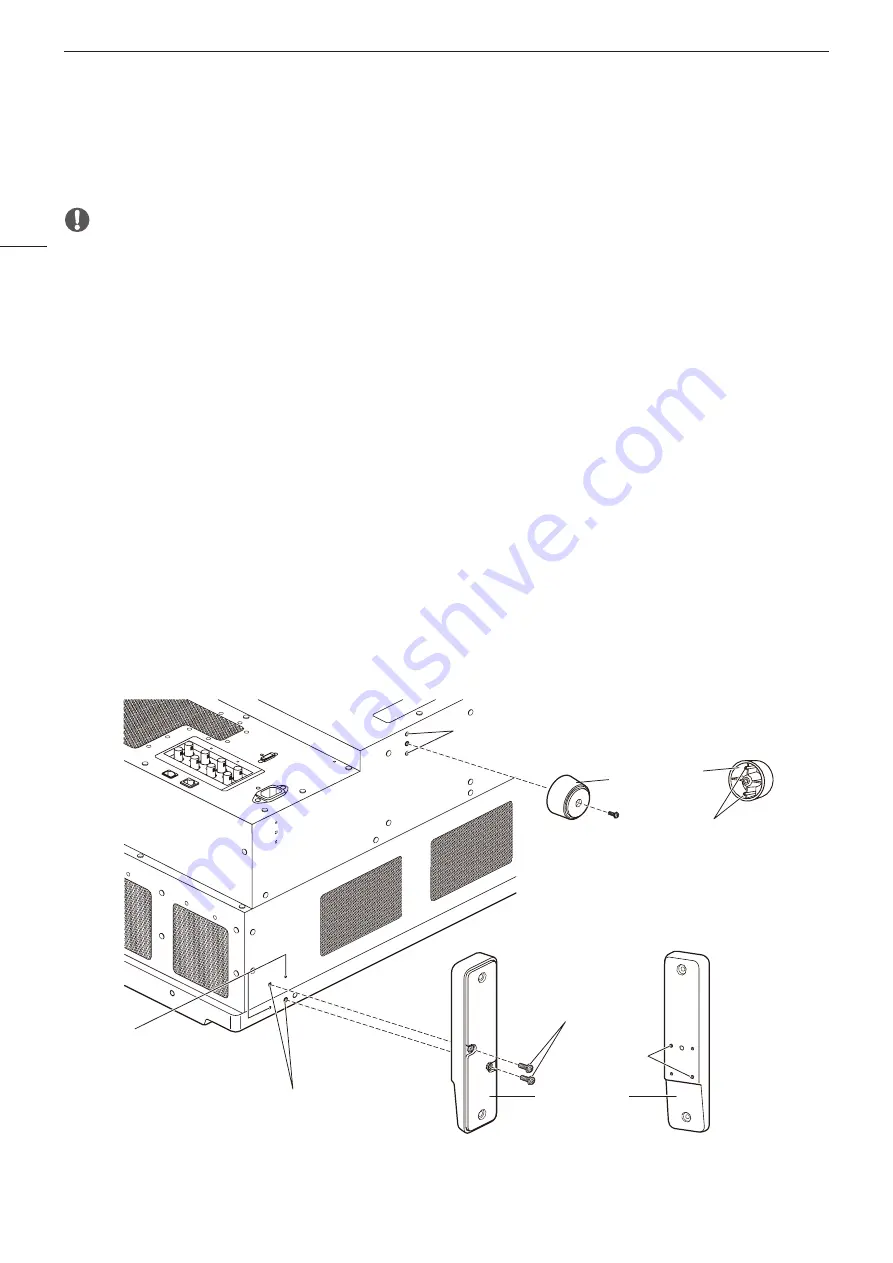
Removing/attaching the stand

The stand can be removed when storing the display on a rack or display shelf.

 CAUTION

•  Make sure to perform this step with at least two people.
•  Use a flat, clear surface when attaching/detaching the stands.
•  The display can tip over if the stand has not been attached.
•  Avoid touching the screen during this step as it may damage it.

Detaching

1  Place the display with the screen facing down on a soft cloth or cushioning material that is larger than the 

display.

2  Front stands (2): Remove the screws holding the stands (2 each). 

Rear stands (4): Remove the screws holding the stands (1 each).

• Do not lose the removed screws. Do not use these screws for other purposes.

Attaching

1  Place the display with the screen facing down on a soft cloth or cushioning material that is larger than the 

display.

2  Align the position of the stand and screw hole on the video display.

• Alight the convex part of the stand and concave part of the video display.

3  Front stands (2): Fasten the screws holding the stands (2 each). 

Rear stands (4): Fasten the screws holding the stands (1 each).

Rear

Screen side

Rear stand

Front stand  
mounting screw hole

Mounting screw

Concave part

Convex part

Concave part

Convex part

Front stand

Summary of Contents for DP-V3120

Page 1: ...ad this guide including the safety and handling precautions Reading this guide will help you learn to use the video display properly Store this guide safely so that you can use it in the future English Video Display Setup Guide ...

Page 2: ...rning on the Main Unit s power 15 Basic operations to use the OSD menu 15 Main specifications Performance 16 Dimensions 18 About the User Manual for the Display Setup Guide this document This describes the items that should be followed to ensure the display can be used correctly and safely and how to install and operate the display Please read before using the display Operation Guide PDF electroni...

Page 3: ...Setup Guide this document Conventions used in this manual Indicates a reference page Note Indicates a note Reference Indicates reference information CAUTION Indicates an item you must observe Trademarks HDMI HDMI logo and High Definition Multimedia Interface are trademarks or registered trademarks of HDMI Licensing Administrator Inc in the U S and other countries VESA is a registered trademark or ...

Page 4: ...Melville NY 11747 U S A Tel No 631 330 5000 For the customers in Canada CAN ICES 3 A NMB 3 A For the customers in Europe Warning This is a class A product In a domestic environment this product may cause radio interference in which case the user may be required to take adequate measures CANON INC 30 2 Shimomaruko 3 chome Ohta ku Tokyo 146 8501 Japan CANON EUROPA N V Bovenkerkerweg 59 1185 XB Amste...

Page 5: ...e The power cord may be damaged exposed or broken wires etc and cause fire or electric shock When using three pronged plugs with a ground connection Always connect the ground prong A short circuit occurring when the ground prong is not connected can cause fire or electric shock The video display s power cable features a three pronged plug Do not touch the power cable or plug during lightning storm...

Page 6: ...use an injury Keep all packaging material out of the reach of children Packaging material tightly wrapped around someone s head can result in strangulation or suffocation CAUTION Denotes the risk of injury Do not place any objects on the video display and do not climb on it The video display can tip or fall and cause injury Do not install the video display on an unstable surface Installing the vid...

Page 7: ...ent is brought into a warm room while it is cold or if the room is heated suddenly condensation may form on the surface or inside the equipment Note that the equipment may be damaged if it is used under such condition If condensation has formed on the surface or inside the equipment do not use the video display as it may get damaged Turn the power off and wait until the condensation has evaporated...

Page 8: ...off 7 Power indicator 8 USB port For connecting USB memories HUBs color grading controllers Tangent Wave s Element Tk or wireless LAN devices Wi Fi adapters 9 Headphone terminal About the power indicator Displays the status of the main unit The power indicator will flash during firmware updates or when an error is detected even if it is set to Off Off when power supply is not connected Green lit w...

Page 9: ...Inputs the HDMI signal CAUTION Do not use the HUB when connecting a wireless LAN adapter Wi Fi adapter to a USB terminal The video display may not work For safety do not connect any connector that may have excessive voltage to the terminal of the video display when connecting peripheral devices Pass through SD SDI signals are not output correctly Note About USB Memory Both FAT16 and FAT32 USB memo...

Page 10: ...he table or desk is strong enough to carry the weight of the main unit For safety make sure to perform this step with at least two people Avoid touching the screen during this step as it may damage it For safety reasons when using the display for extended periods of time in a situation where it is subject to vibrations shocks or is tilted when moving in a live broadcast vehicle etc take additional...

Page 11: ...he wall has sufficient strength If necessary apply reinforcement Also make sure to check the load capacity of the stand or wall mount bracket When the video display is placed on a rack or display stand and ventilation around it is blocked by equipment placed above or below or in a surrounding area the operating temperature may increase causing a failure or overheating In order to maintain the oper...

Page 12: ...nds 2 Remove the screws holding the stands 2 each Rear stands 4 Remove the screws holding the stands 1 each Do not lose the removed screws Do not use these screws for other purposes Attaching 1 Place the display with the screen facing down on a soft cloth or cushioning material that is larger than the display 2 Align the position of the stand and screw hole on the video display Alight the convex p...

Page 13: ...ace with the holder 3 The holder should always be fastened in the position as shown in the illustration 4 Press the holder against the main unit 4 Make sure that there is no slack A Pulling the holder lock lever in the direction of the arrow will allow you to adjust the holder position 5 Detaching 1 Pull the holder lever in the direction of the arrow 6 and remove the AC power cord clamp from the A...

Page 14: ... RAW signal frequency exceeds 30 00P it becomes a dual connection Each input terminal is compatible with through output When signals are input from Input IN A connect the cable to the SDI OUT terminal of Input A SDI input terminal HDMI input terminal Signals that can be connected to the SDI input terminal Input signal Input terminal Quad Link Square Division 12G 6G 3G HD SDI Top left Mapping signa...

Page 15: ...y Wait at least 10 minutes after turning on the power before use Basic operations to use the OSD menu The video display settings are changed from the OSD menu Using buttons and jog dial on the video display you can adjust image quality and configure settings for input signals MENU button Opens closes the OSD menu or moves up one level in a menu RESET button Resets the items to be adjusted using th...

Page 16: ...ing Approximately 840 W At factory shipment Approximately 175 W Environmental Conditions Operating Temperature and humidity 5 35 C 41 95 F 20 85 RH no condensation Recommended range of temperature and humidity 15 30 C 59 86 F 20 to 80 RH no condensation Pressure 700 1060 hPa Storage Transporting Temperature and humidity 20 40 C 4 104 F 10 85 RH no condensation 41 60 C 105 140 F 10 30 RH no condens...

Page 17: ...G 6G 3G HD SDI 4 pass thru Head phone 1 stereo mini jack Supported impedance 32 Ω to 64 Ω Others USB 1 USB A receptacle terminal Universal Serial Bus Specification Revision 2 0 compliant LS Low Speed FS Full Speed HS High Speed mode compatible Compliant with Enhanced Host Controller Interface Specification for Universal Serial Bus Revision 1 0 LAN 1 RJ 45 terminal Compliant with IEEE802 3 10BASE T...

Page 18: ...imensions 615 24 2 749 29 5 470 18 5 492 19 4 200 7 9 200 7 9 615 24 2 121 5 4 8 281 5 11 1 161 7 6 4 21 1 0 8 112 5 4 4 15 0 6 4 M6 Depth 8 0 3 Max Center of panel 4 4 5 0 2 25 3 1 0 335 13 2 295 11 6 Unit mm inch Front Rear Side Bottom ...

Page 19: ...on USA will have no responsibility Canon USA shall have no responsibility under this limited warranty for use of the Equipment in conjunction with incompatible peripheral equipment and or incompatible software Non Canon brand peripheral equipment and software which may be distributed with or be factory loaded on the Equipment are sold AS IS without warranty of any kind by Canon USA including any i...

Page 20: ...S EXPENSE FOR SUBSTITUTE EQUIPMENT OR SERVICE STORAGE CHARGES LOSS OR CORRUPTION OF DATA INCLUDING WITHOUT LIMITATION LOSS OR CORRUPTION OF DATA STORED ON THE EQUIPMENT S HARD DRIVE OR ANY OTHER SPECIAL INCIDENTAL OR CONSEQUENTIAL DAMAGES CAUSED BY THE USE MISUSE OR INABILITY TO USE THE EQUIPMENT REGARDLESS OF THE LEGAL THEORY ON WHICH THE CLAIM IS BASED AND EVEN IF CANON USA HAS BEEN ADVISED OF T...

Page 21: ...e software as to which items Canon Canada will have no responsibility Canon Canada shall have no responsibility under this limited warranty for use of the Equipment in conjunction with incompatible computer equipment peripheral equipment and or incompatible software Non Canon brand peripheral equipment and software which may be distributed with or be factory loaded on the Equipment are sold AS IS ...

Page 22: ...ORAGE CHARGES LOSS OR CORRUPTION OF DATA INCLUDING WITHOUT LIMITATION LOSS OR CORRUPTION OF DATA STORED ON THE EQUIPMENT S HARD DRIVE OR ANY OTHER SPECIAL INCIDENTAL OR CONSEQUENTIAL DAMAGES CAUSED BY THE USE MISUSE OR INABILITY TO USE THE EQUIPMENT REGARDLESS OF THE LEGAL THEORY ON WHICH THE CLAIM IS BASED AND EVEN IF CANON CANADA HAS BEEN ADVISED OF THE POSSIBILITY OF SUCH DAMAGES NOR SHALL RECO...

Page 23: ...TED KINGDOM Canon UK Ltd Unit 160 Centennial Park Centennial Avenue Elstree Hertfordshire WD6 3SG 020 7660 0186 Canon Inc 30 2 Shimomaruko 3 chome Ohta ku Tokyo 146 8501 Japan Canon Europa N V Bovenkerkerweg 59 1185 XB Amstelveen The Netherlands http www canon europe com PUB MIM 0060 A MIE 0022 000 CANON INC 2019 ...

Reviews: