background image

Clutch, Motor, PCB, Other

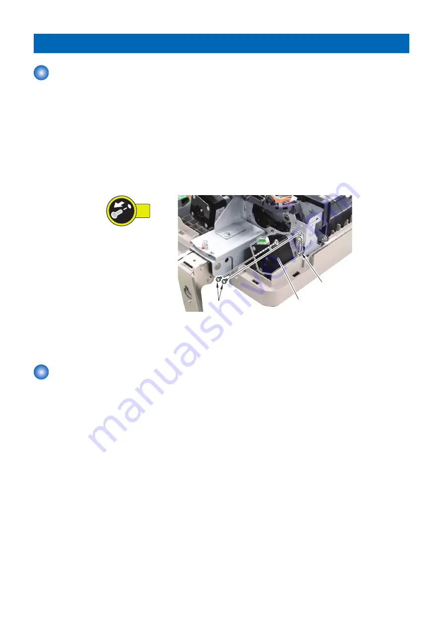
 Removing the Pickup Motor (M1)

■ Preparation

1. Remove the Rear Cover.

“Removing the Rear Cover” on page 45

2. Remove the Clutch unit.

“Removing the Pickup Clutch/Registration Clutch (CL1/CL2)” on page 62

■ Procedure

1. Remove the Pickup motor [1].

• 2 Screws [2]
• 1 Spring [3]

2x

[2]

[3]

[1]

■ Actions after Replacement

1. Adjusting the Magnification.

“Adjusting the Magnification” on page 103

 Removing the Read Motor (M2)

■ Preparation

1. Remove the Rear Cover.

“Removing the Rear Cover” on page 45

4. Parts Replacement and Cleaning

61

Summary of Contents for DADF-AV1

Page 1: ...Revision 2 0 DADF AV1 Service Manual ...

Page 2: ...g or short period Canon will issue a new edition of this manual The following paragraph does not apply to any countries where such provisions are inconsistent with local law Trademarks The product names and company names used in this manual are the registered trademarks of the individual companies Copyright This manual is copyrighted with all rights reserved Under the copyright laws this manual ma...

Page 3: ... door and closing the delivery unit door which results in supplying the machine with power 2 In the digital circuits 1 is used to indicate that the voltage level of a given signal is High while 0 is used to indicate Low The voltage value however differs from circuit to circuit In addition the asterisk as in DRMD indicates that the DRMD signal goes on when 0 In practically all cases the internal me...

Page 4: ...12 Outline 12 Forward Pickup Delivery Operation 12 Forward Pickup Reverse Delivery Operation 13 Document Pickup Feed 18 Basic Operation 18 Pickup Roller Assembly and Separation Roller 19 Document Reversing 20 Basic Operation 20 Document Delivery 22 Document Detection 23 Outline 23 Initial Document Size Detection 23 Mixed width document size detection 25 Detecting Jams 27 Power Supply 29 Stamp Oper...

Page 5: ...Removing the Left Hinge 54 Sensor 56 Removing the Different Width Sensor PCB PCB3 56 Removing the Sensor SR1 SR2 SR3 56 Clutch Motor PCB Other 61 Removing the Pickup Motor M1 61 Removing the Read Motor M2 61 Removing the Pickup Clutch Registration Clutch CL1 CL2 62 Removing the ADF Driver PCB PCB1 63 Removing the Document Set LED PCB PCB2 63 Removing the Right Hinge 64 Removing the Platen Roller 6...

Page 6: ...can Glass 95 Checking After Installation 96 Disposal Parts 96 Operation Check 96 Adjustment 97 Overview of Adjustment 97 Preparation or Creation of Test Chart 97 Adjusting the Height 97 Adjusting the Perpendicularity 100 Adjusting the Reading Position 102 Adjusting the Magnification 103 Adjusting the Image Position Main Scanning Direction 104 Adjusting the Image Position Sub Scanning Direction 105...

Page 7: ...Safety Precautions Notes Before Servicing 2 Points to Note at Cleaning 2 Notes on Assembly Disassembly 2 ...

Page 8: ...not specially instructed reverse the order of disassembly to reinstall 3 Ensure to use the right screw type length diameter etc at the right position when assembling 4 To keep electric conduction binding screws with washers are used to attach the grounding wire and the varistor Ensure to use the right screw type when assembling 5 Unless it is specially needed do not operate the device with some pa...

Page 9: ...Product Overview 1 Features 4 Specifications 5 Name of Parts 6 ...

Page 10: ... engaging disengaging the Pickup roller assembly and the Separation roller Improvement of paper curl detection by the modification the Document length sensor Installation of the Document delivery Lamp function 1 Product Overview 4 ...

Page 11: ...fferent types of paper 64 to 81 g m2 Document longer than 432 mm Single sided one sheet feed 60 to 90 g m2 Document size AB configuration B6 A5R A5 B5R B5 A4R A4 B4 A3 Inch configuration 11 17 LGL LTR LTRR STMT STMTR 8K 16K Width 140 to 297 mm Length 128 to 432 mm It is available when the operator holds long documents between 432mm and 630mm Document supply tray capacity 100 sheets 80 g m2 Documen...

Page 12: ... Rear Small Cover 7 Front Cover 4 Slide guide Cross Section 3 4 1 2 6 7 9 8 5 No Name No Name 1 Lower registration roller 6 Lower delivery reversal roller 2 Upper registration roller 7 Lead roller 2 upper 3 Pickup roller assembly 8 Platen roller 4 Separation roller 9 Lead roller 1 upper 5 Upper delivery reversal roller 1 Product Overview 6 ...

Page 13: ... Controls 11 Basic Operation 12 Document Pickup Feed 18 Document Reversing 20 Document Delivery 22 Document Detection 23 Detecting Jams 27 Power Supply 29 Stamp Operation If equipped with the Stamp Unit 30 Original Output Indicator 31 Upgrading 32 ...

Page 14: ...dth sensor PCB SL2 Stamp solenoid PCB4 Document width sensor PCB M1 Pickup motor PCB5 Document delivery LED PCB M2 Read motor Roller Layout 3 5 4 1 2 6 7 8 9 13 12 10 11 No Name No Name 1 Lower registration roller 8 Lead roller 2 lower 2 Upper registration roller 9 Lead roller 2 upper 3 Feed roller 10 Platen roller 4 Separation roller 11 Lead roller 5 Pickup roller 12 Lead roller 1 lower 6 Upper d...

Page 15: ...reversal timing SR5 Document set sensor Document set detection SR6 Cover open closed sensor Open close of Feeder Cover SR7 Document length sensor 1 Document size detection length SR8 Document length sensor 2 SR9 Different width sensor 1 Document size detection width SR10 Different width sensor 2 SR11 Different width sensor 3 SR12 Different width sensor 4 SR13 Document width sensor 1 SR14 Document ...

Page 16: ...t the power of the Pickup motor to the Lower registration roller Electric Circuit Diagram Electric circuits of this machine are controlled by the host machine The Main Controller PCB of the host machine detects the input signals from sensors to output DC load drive signal such as motors solenoids and clutches at the predetermined timing The ADF driver PCB PCB1 does not have a memory space The data...

Page 17: ...page 20 Document Delivery Document Delivery on page 22 Document Detection Document Detection on page 23 Detecting Jams Detecting Jams on page 27 Power Supply Power Supply on page 29 Stamp Operation Stamp Operation If equipped with the Stamp Unit on page 30 Original Output Indicator Original Output Indicator on page 31 Upgrading Upgrading on page 32 2 Technical Explanation 11 ...

Page 18: ...d feed Reverse delivery Picks up reads reverses and delivers a document Double sided document Duplex printing Double sided document Simplex printing Forward Pickup Delivery Operation Simplex read operation when two document sheets are placed Document Pickup of first document sheet Formation of loop Start for reading of the first document sheet Reading of first document sheet Pickup of second docum...

Page 19: ...t sheet Completion of delivery of first document sheet Completion of delivery of the second document sheet End of job Start of reading of second document sheet Forward Pickup Reverse Delivery Operation Duplex read operation when two document sheets are placed 2 Technical Explanation 13 ...

Page 20: ...Position to start of reading of first document sheet Start of reading of front side of first document sheet End of reading of first document sheet Stop after feeing the first document sheet to reversal position To next Document 2 Technical Explanation 14 ...

Page 21: ...document sheet Stop after feeding the first document sheet to reversal position Idle feed of first document sheet Removal of idle registration loop at the first document sheet Re pickup Release of the Lower delivery reversal roller To next Completion of reading of reverse side at the first document sheet Pressurization of the Lower delivery reversal roller 2 Technical Explanation 15 ...

Page 22: ...cond document sheet End of reading of front side of second document sheet Stop after feeding the second document sheet to reversal position Delivery of first document sheet Removal of registration loop of reverse side at the second document sheet Re pickup Release of the Lower delivery reversal roller To next 2 Technical Explanation 16 ...

Page 23: ...e second document sheet to reversal position Removal of idle registration loop at the second document sheet Re pickup Release of the Lower delivery reversal roller Delivery of second document sheet Pressurization at the Lower delivery reversal roller Completion of delivery of second document sheet end of job 2 Technical Explanation 17 ...

Page 24: ...eding a document M1 Document Pickup roller ศ㞳ࣟ ࣛ Stopper CL1 CL1 Pickup roller ศ㞳ࣟ ࣛ Separation roller M1 Formation of loop During Pickup Operation the Lower registration roller is stopped rotating while moving a document against the Upper Lower registration rollers and then form a loop Thus it prevents a document from skewing Upper Lower registration roller Loop Feed The Pickup motor M1 drives th...

Page 25: ...ckup Roller Assembly and Separation Roller The Pickup roller assembly consists of the Pickup roller and the Feed roller When the start key is pressed or a document pickup signal is input the Pickup motor M1 drives to lower the Pickup roller assembly through the Pickup clutch CL1 and then the Pickup roller and the Feed roller rotates to feed a document to the Registration roller The Pickup roller a...

Page 26: ...r Platen roller Read roller 2 Upper Read roller 1 Upper M2 M2 Reversal Feed 1 After the trailing edge of a fed document passes the Delivery reversal sensor SR3 the Read motor M2 stops Thus a document stops at the reverse point The Read motor M2 drives in reverse direction to feed a document to the Registration roller and then it stops After that the Release solenoid SL1 turns on to release the Low...

Page 27: ...Read roller 1 Upper Upper delivery reversal roller SL1 CL2 Reading start point Lower registration roller M2 M1 SL1 M2 2 Technical Explanation 21 ...

Page 28: ...very A document is delivered by the Lead roller 2 upper and the Upper delivery reversal roller driven by the Read motor M2 SL1 Upper delivery reversal roller SL1 M2 Read roller 2 Upper M2 2 Technical Explanation 22 ...

Page 29: ...gth Document length is detected while feeding Registration sensor SR1 Read sensor SR2 Width Detects the maximum document width on the Document supply tray Document width sensor1 2 3 SR13 SR14 SR15 Document width is detected while feeding Different width sensor 1 2 3 4 SR9 SR10 SR11 SR12 Initial Document Size Detection Initial document size is detected when a document is placed on the Document supp...

Page 30: ...re than 143 9 and 165 0 or less OFF ON ON ON ON A5R A5R OFF ON A5R A5R ON OFF A5R A5R OFF OFF A5R A5R A5R More than 165 0 and 196 0 or less OFF OFF ON ON ON B5R B5R OFF ON B5R B5R ON OFF B5R B5R B5R OFF OFF B6 B6 B6 More than 196 0 and 213 9 or less ON OFF ON ON ON A4R A4R OFF ON A4R A4R ON OFF A4R A4R A4R OFF OFF A5 A5 A5 More than 213 9 and 236 5 or less ON ON ON ON ON LGL LGL A4R OFF ON LGL A4R...

Page 31: ...imum width is detected by the Different width sensor 1 2 3 4 SR9 SR10 SR11 SR12 Document length is detected by ON state on the Read sensor SR2 and OFF state on the Registration sensor SR1 Each document size is determined by the combination of the ON OFF states on these sensors SR2 SR9 SR12 SR10 SR11 SR13 SR15 SR14 SR1 Same series mixed width document combination Same series of size AB configuratio...

Page 32: ...A C B5R 182 0 C B6 C Inch configuration Mixed Different series of size LGL LTRR STMT STMTR Maximum size Width mm 215 9 139 7 11 17 279 0 A B B LTR A B A C LGL 215 9 C LTRR C STMT C Item Contents A Combination assured B Not assured Possible to feed C Not assured Possible to have original jam Out of Specifications 2 Technical Explanation 26 ...

Page 33: ...Read sensor SR2 01 0050 STNRY Read sensor SR2 01 0013 DELAY Delivery reversal sensor SR3 01 0053 DELAY Delivery reversal sensor SR3 01 0014 STNRY Delivery reversal sensor SR3 01 0054 STNRY Delivery reversal sensor SR3 01 0071 Sequence 01 0090 DADF OP Copyboard cover open closed sensor 1 At copy mode select the Pickup Cas sette PS_N1 01 0091 DADF OP Copyboard cover open closed sensor 1 other than t...

Page 34: ...e the machine when a problem which requires the machine moves to limited functions mode occurs If an error occurs for some reasons a jam message is displayed to make the user to perform jam removal The troubleshooting from this jam cord is not possible 2 Technical Explanation 28 ...

Page 35: ...er Supply The power supply lines are shown below This machine power is supplied from the host machine 24V 5V 5V 24V Motor Solenoid Clutch Sensor ADF driver PCB Host machine J9 J5 2 Technical Explanation 29 ...

Page 36: ... scan mode a document is stamped indicating that a document is already read or sent The Stamp solenoid SL2 drives the Stamper The Stamp solenoid SL2 is driven by the signal from the ADF driver PCB PCB1 Stamp solenoid drive signal ADF driver PCB Document Stamp solenoid Stamper 2 Technical Explanation 30 ...

Page 37: ...B5 lights ON to prevent from leaving a document The LED keeps lighting for 10 seconds and then turns OFF PCB5 Related service mode ON OFF of DADF delivery LED Connecting to iR ADV devices COPIER OPTION CUSTOM DFEJCLED Connecting to iR devices COPIER OPTION FNC SW DFEJCLED 2 Technical Explanation 31 ...

Page 38: ...Upgrading Outline Since this equipment is not equipped CPU upgrading is not possible by itself Upgrade it on the host machine 2 Technical Explanation 32 ...

Page 39: ...Periodical Service 3 List of Work for Servicing 34 ...

Page 40: ...TAMP User maintenance Replacing the Stamp on page 53 4 Left hinge FE3 5484 1 CR 150 000 times DF HNG L Number of open close Removing the Left Hinge on page 54 5 Registration roller 1 CL As required Clean with a cloth which is dampened with water or neutral detergent and squeezed hard and then wipe with a dry cloth 6 Feed Guide Dust col lecting tape 1 CL As required 7 Delivery reverse roller 1 CL A...

Page 41: ...lacement and Cleaning 4 List of Parts 36 Removing this Machine from the Host Machine 41 External Cover 44 Main Unit 49 Periodic Replacing Parts Durable Parts Cleaning Parts 52 Sensor 56 Clutch Motor PCB Other 61 ...

Page 42: ...emoving the Front Cover on page 44 2 Rear Cover Removing the Rear Cover on page 45 3 Feeder Cover Removing the Feeder Cover on page 46 4 Rear Small Cover Removing the Rear Cover on page 45 5 Inner Cover Removing the Inner Cover on page 47 4 Parts Replacement and Cleaning 36 ...

Page 43: ...on page 49 Consumable Parts Requiring Periodic Replacement and Cleaning Points 3 2 1 4 No Name Reference 1 Pickup roller assembly Removing the Pickup Roller Assembly on page 52 2 Separation roller Removing the Separation Roller on page 53 4 Parts Replacement and Cleaning 37 ...

Page 44: ... solenoid SL2 Stamp solenoid CL1 Pickup clutch Removing the Pickup Clutch Registration Clutch CL1 CL2 on page 62 CL2 Registration clutch PCB1 ADF driver PCB Removing the ADF Driver PCB PCB1 on page 63 PCB2 Original set indicator Document supply tray Removing the Document Set LED PCB PCB2 on page 63 PCB3 Different width sensor PCB Feeder Cover Removing the Different Width Sensor PCB PCB3 on page 56...

Page 45: ...or SR7 Document length sensor 1 Document supply tray SR8 Document length sensor 2 Document supply tray SR9 Different width sensor 1 Feeder Cover Removing the Different Width Sensor PCB PCB3 on page 56 SR10 Different width sensor 2 Feeder Cover SR11 Different width sensor 3 Feeder Cover SR12 Different width sensor 4 Feeder Cover SR13 Document width sensor 1 Document supply tray SR14 Document width ...

Page 46: ...Other 1 2 No Name Reference 1 Right hinge Removing the Right Hinge on page 64 2 Platen roller Removing the Platen Roller on page 65 4 Parts Replacement and Cleaning 40 ...

Page 47: ...NNER ADVANCE 4500 Series imageRUNNER ADVANCE C3500 Series 1 Remove the Cover of Reader 1 2 Rubber Caps 2 2 Screws 3 2x 1 3 2 2 Disconnect the Grounding Cable 1 2 Connectors 2 1 Screw 3 2 Wire Saddles 4 1x 2x 1 2 3 4 3 Open the ADF 4 Parts Replacement and Cleaning 41 ...

Page 48: ...When holding this equipment be careful not to touch the Platen roller 3 2 Screws 2 2x 1 3 2 For imageRUNNER C3025 C3020 Series 1 Remove the Cover of Reader 1 2 Rubber Caps 2 2 Screws 3 2x 2 1 3 4 Parts Replacement and Cleaning 42 ...

Page 49: ...endicularity Adjusting the Perpendicularity on page 74 3 Adjusting the Reading Position Adjusting the Reading Position on page 78 4 Adjusting the Magnification Adjusting the Magnification on page 79 5 Adjusting the Image Position Main Scanning Direction Adjusting the Image Position Main Scanning Direction on page 80 6 Adjusting the Image Position Sub Scanning Direction Adjusting the Image Position...

Page 50: ...External Cover Removing the Front Cover Procedure 1 Open the Feeder Cover 1 1 2 Remove the screw 1 1x 1 3 Open the ADF 4 Remove the 2 screws 2 2x 2 4 Parts Replacement and Cleaning 44 ...

Page 51: ...5 Close the ADF 6 Remove the Front Cover 1 3 Hooks 2 1 2 2 Removing the Rear Cover Procedure 1 Open the Feeder Cover 1 1 4 Parts Replacement and Cleaning 45 ...

Page 52: ... Remove the Rear Cover 1 2 Screws 2 2 Claws 3 2x 2x 1 2 3 Removing the Feeder Cover Preparation 1 Remove the Rear Cover Removing the Rear Cover on page 45 2 Remove the Front Cover Removing the Front Cover on page 44 4 Parts Replacement and Cleaning 46 ...

Page 53: ...4 2 Remove the Feeder Cover 1 1 Screw 2 1 Positioning Pin 3 CAUTION Be careful not to hang the cables while putting the rear cables through the hole at the plate 1x 3 2 1 Removing the Inner Cover Preparation 1 Remove the Pickup roller assembly Removing the Pickup Roller Assembly on page 52 4 Parts Replacement and Cleaning 47 ...

Page 54: ... Procedure 1 Remove the Inner Cover 1 1 Screw 2 2 Claws 3 1x 2x 1 2 3 3 4 Parts Replacement and Cleaning 48 ...

Page 55: ... page 45 2 Remove the ADF from the host machine Removing this Machine from the Host Machine on page 41 3 Remove the Feeder Cover Removing the Feeder Cover on page 46 Procedure 1 Remove the Tray holder 1 1 Screw 2 1x 1 2 2 Remove the Grounding Wire 1 1 Screw 2 1x 1 2 4 Parts Replacement and Cleaning 49 ...

Page 56: ...5 1x 1 1x 2 4 5 3 5 Remove the Read motor Removing the Read Motor M2 on page 61 6 Remove the Left hinge Removing the Left Hinge on page 54 7 Remove the Pickup clutch Registration clutch Removing the Pickup Clutch Registration Clutch CL1 CL2 on page 62 8 Remove the Pickup motor Removing the Pickup Motor M1 on page 61 4 Parts Replacement and Cleaning 50 ...

Page 57: ...9 Remove the harness guide 1 1 Screw 2 1 Connector 3 1x 2x 3 2 1 10 Remove the Feed assembly 1 6 Screws 2 6x 2 2 2 1 4 Parts Replacement and Cleaning 51 ...

Page 58: ...ving the Pickup Roller Assembly Procedure 1 Open the Feeder cover 1 1 2 Remove the Pickup roller assembly 1 1 3 When replacing the Pickup roller assembly with a new one clear the parts counter COPIER COUNTER DRBL 2 DF PU RL 4 Parts Replacement and Cleaning 52 ...

Page 59: ...emove the Separation roller 1 1 3 When replacing the Separation roller with a new one clear the parts counter COPIER COUNTER DRBL 2 DF SP RL Replacing the Stamp Procedure 1 Open the Feeder Cover and Separation guide 2 Remove the Stamper 1 4 Parts Replacement and Cleaning 53 ...

Page 60: ...in the Stamper until it clicks 5 When replacing the Stamper with a new one clear the parts counter COPIER COUNTER DRBL 2 STAMP Removing the Left Hinge Preparation 1 Removing the Rear Cover Removing the Rear Cover on page 45 2 Remove the ADF from the host machine Removing this Machine from the Host Machine on page 41 Procedure 1 Open the Feeder cover 1 1 4 Parts Replacement and Cleaning 54 ...

Page 61: ...CAUTION Be careful not to drop the Left hinge Hold it while removing the screws from it 6x 1 2 2 2 2 3 When replacing the Left hinge with a new one clear the parts counter COPIER COUNTER DRBL 2 DF HNG L 4 Parts Replacement and Cleaning 55 ...

Page 62: ...nner Cover on page 47 Procedure 1 Remove the sensor holder 1 3 Screws 2 3x 2 1 2 Remove the Different width sensor PCB 1 1 Connector 2 3 Claws 3 1x 3x 2 3 3 3 1 Removing the Sensor SR1 SR2 SR3 Preparation 1 Remove the Feed assembly Removing the Feed Assembly on page 49 4 Parts Replacement and Cleaning 56 ...

Page 63: ... fixing plate 1 3 Screws 2 3x 1 2 2 2 2 Turn over the Feed assembly remove the following parts 1 Resin ring 1 1 Flange 2 1 Pulley 3 1 E ring 4 1 Bearing 5 1 Gear 6 1 Bushing 7 1 2 3 4 5 7 6 4 Parts Replacement and Cleaning 57 ...

Page 64: ...3 Remove the Platen roller unit 1 2 Claws 2 2x 2 1 2 4 Remove the Cover 1 2 Screws 2 2x 2 1 4 Parts Replacement and Cleaning 58 ...

Page 65: ...Lead roller 2 upper 1 1 Resin ring 2 1 Flange 3 1 Pulley 4 1 E ring 5 1 Bearing 6 1 Gear 7 1 Bushing 8 3 2 4 5 6 7 8 1 6 Remove the Sensor mount 1 2 Screws 2 2 Claws 3 2x 2x 1 2 3 4 Parts Replacement and Cleaning 59 ...

Page 66: ...7 Remove the Sensors 1 3 Connectors 2 1 SR1 1 SR2 1 SR3 3x 4 Parts Replacement and Cleaning 60 ...

Page 67: ...g the Pickup Clutch Registration Clutch CL1 CL2 on page 62 Procedure 1 Remove the Pickup motor 1 2 Screws 2 1 Spring 3 2x 2 3 1 Actions after Replacement 1 Adjusting the Magnification Adjusting the Magnification on page 103 Removing the Read Motor M2 Preparation 1 Remove the Rear Cover Removing the Rear Cover on page 45 4 Parts Replacement and Cleaning 61 ...

Page 68: ...usting the Magnification on page 103 Removing the Pickup Clutch Registration Clutch CL1 CL2 Preparation 1 Remove the Rear Cover Removing the Rear Cover on page 45 2 Remove the Feeder Cover Removing the Feeder Cover on page 46 Procedure 1 Remove the Clutch support plate 1 3 Connectors 2 2 Screws 3 2x 3x 3 2 2 1 4 Parts Replacement and Cleaning 62 ...

Page 69: ... Preparation 1 Remove the Rear Cover Removing the Rear Cover on page 45 Procedure 1 Remove the ADF driver PCB 1 10 Connectors 2 2 Screws 3 2x 10x 3 1 2 2 2 2 Removing the Document Set LED PCB PCB2 Preparation 1 Remove the Inner cover Removing the Inner Cover on page 47 4 Parts Replacement and Cleaning 63 ...

Page 70: ...1 2 Remove the LED PCB 1 1 Screw 2 1 Connector 3 1x 1x 1 2 3 Removing the Right Hinge Preparation 1 Remove the ADF from the host machine Removing this Machine from the Host Machine on page 41 Procedure 1 Turn over the ADF 4 Parts Replacement and Cleaning 64 ...

Page 71: ...nge 1 2 Screws 2 2x 1 2 Removing the Platen Roller Preparation 1 Remove the Feed assembly Removing the Feed Assembly on page 49 Procedure 1 Remove the fixing plate 1 3 Screws 2 3x 1 2 2 2 4 Parts Replacement and Cleaning 65 ...

Page 72: ...d assembly remove the following parts 1 Resin ring 1 1 Flange 2 1 Pulley 3 1 E ring 4 1 Bearing 5 1 Gear 6 1 Bushing 7 1 2 3 4 5 7 6 3 Remove the Platen roller unit 1 2 Claws 1 2x 2 1 2 4 Parts Replacement and Cleaning 66 ...

Page 73: ...4 Remove the Platen roller 1 2 Screws 2 1 Plate 3 1 Platen roller holder front 4 1 Bushing 5 1 Gear 6 1 Platen roller holder rear 7 2x 1 7 6 2 3 4 5 2 4 Parts Replacement and Cleaning 67 ...

Page 74: ...Adjustment 5 Overview 69 Basic Adjustment 70 ...

Page 75: ... Position Adjusting the Reading Position on page 78 4 Adjusting the Magnification Adjusting the Magnification on page 79 5 Adjusting the Image Position Horizontal Scanning Direction Adjusting the Image Position Main Scan ning Direction on page 80 6 Adjusting the Image Position Leading Edge Adjusting the Image Position Sub Scanning Direction on page 81 7 Adjusting the White Level Adjusting the Whit...

Page 76: ...agnification 5 Adjusting the Image Position Main Scanning Direction 6 Adjusting the Image Position Sub Scanning Direction 7 Adjusting the White Level Adjusting the Height Check the Left Hinge Height When Visual Check 1 Close the DADF and check whether the front and rear ADF scan glass spacers are in close contact with the ADF scan glass NOTE If visual check is difficult perform the check with refe...

Page 77: ...hat the sheet is nearly hidden and then close the DADF NOTE By placing the paper slip as instructed it does not interfere the soundproofing sheet stuck on the bottom of the DADF when closing it Soundproofing Sheet CAUTION Use plain paper Set paper so that it does not reach the document reader Paper Protrusion Sheet Document reader Protrusion Sheet Document reader 5 Adjustment 71 ...

Page 78: ...is felt 3 Check the front left height of the DADF Set paper against the protrusion in such a manner that the sheet is nearly hidden and then close the DADF CAUTION Set paper so that it does not reach the document reader Protrusion Sheet Document reader Paper Protrusion Sheet Document reader 5 Adjustment 72 ...

Page 79: ...just the Left Hinge Height 2 Adjust the Right Hinge Height 3 Check the Left Hinge Height Check the height of the Left Hinge If the height is inappropriate adjust it again When both sides are floating 1 Adjust the Left Hinge Height 2 Adjust the Right Hinge Height 3 Adjust the Left Hinge Height 4 Check the Right Hinge Height Check the height of the Right Hinge If the height is inappropriate adjust i...

Page 80: ...ting screw counterclockwise to bring the rear spacer closer to the glass Hinge height adjusting screw Lock nut Adjusting the Right Hinge Height 1 Adjust the height with the right hinge height adjusting screw CAUTION Loosen the lock nut before adjustment and tighten it after adjustment Turning the adjusting screw clockwise raises the right side height of the DADF Turning the adjusting screw counter...

Page 81: ...ing edges of the test chart and copy Measure dimensions A and B on the test chart and dimensions A and B on the copy If A B is not same as A B go step 3 and following steps B A Test chart B A Feed direction Copy Feed direction 5 Adjustment 75 ...

Page 82: ...slide the hinge to the front or rear with reference to the marking off line to adjust the perpendicularity 1x For B A Slide the hinge to rear side For A B Slide the hinge to front side 4 Tighten the fixing screw loosened in step 3 1x 5 Adjustment 76 ...

Page 83: ...5 Remove the White Plate 6 Place the White Plate on the Copyboard Glass by aligning it with the Index Sheet 5 5 5217 7 Close the DADF and then open it again 5 Adjustment 77 ...

Page 84: ...hat there is no gap between the White Plate and the Index Sheet As a guide it should be 0 3 mm or less White Plate Index Sheet Reader Unit White Plate Index Sheet Reader Unit White Plate Index Sheet Reader Unit White Plate Index Sheet Reader Unit Adjusting the Reading Position 1 Execute the following item in the service mode COPIER FUNCTION INSTALL STRD POS 2 Press OK or Yes The scanner to start a...

Page 85: ...tment again 2 If the auto adjustment operation still fails make the manual adjustment with the following service mode COPIER ADJUST ADJ XY STRD POS Change the setting and adjust on the best setting checking the output copy image 3 When the setting value was changed in step 2 write down the new numerical value in the service label Adjusting the Magnification 1 Copy the test chart with the DADF 2 Co...

Page 86: ...ing edge of printed image Trailing edge of test chart If the image is longer 3 When the setting value was changed in step 2 write down the new numerical value in the service label NOTE The service label affixed to the inside of Reader Front Cover Adjusting the Image Position Main Scanning Direction 1 Copy the test chart with the DADF 2 Compare the horizontal registration between the copy and the t...

Page 87: ...r side of test chart image Rear side of printed image If the image is displaced toward front 3 When the setting value was changed in step 2 write down the new numerical value in the service label NOTE The service label affixed to the back of Reader Front Cover Adjusting the Image Position Sub Scanning Direction 1 Copy the test chart with the DADF 2 Compare the leading edge registration between the...

Page 88: ... leading edge 3 When the setting value was changed in step 2 write down the new numerical value in the service label NOTE The service label affixed to the back of Reader Front Cover Adjusting the White Level NOTE 1 This is a item of adjustment in which the white level of images made in stream reading mode are matched with the white level of images made in book mode If this adjustment is skiped the...

Page 89: ...ecute the following item in the service mode COPIER FUNCTION CCD DF WLVL2 4 Press OK or Yes Automatic adjustment starts duplex stream reading 5 If adjustment fails perform steps 1 to 4 again 6 Select the following item in the service mode to check the value and write down the new adjustment value on the service label COPIER ADJUST CCD DFTAR R COPIER ADJUST CCD DFTAR G COPIER ADJUST CCD DFTAR B NOT...

Page 90: ...Installation 6 Checking Before Installation 85 Unpacking 86 Checking the Contents 87 Installation Procedure 88 Checking After Installation 96 Adjustment 97 ...

Page 91: ...both turned OFF and then disconnect the power plug from the outlet Points to Note on Installation Marked portion When tightening the screws do not tighten them too tightly Otherwise there is a risk of damage and deformation of screw holes Product Name Safety regulations require the product s name to be registered In some regions where this product is sold the following name may be registered inste...

Page 92: ...ct it from vibration and impact during transit Remove all such tapes and cushioning materials as instructed below before installing this equipment 1 Take out the DADF from the carton NOTE The weight of the DADF is about 8 2kg 2 Remove all the tapes and the cushioning materials from the DADF 6 Installation 86 ...

Page 93: ...pcs 6 Screw RS Tightening M3x8 1pc 7 Wire Saddle small 2pcs 1 8 Wire Saddle large 1pc 1 9 Finger Pinch Caution Label 1 1pc 2 10 Finger Pinch Caution Label 2 1pc 2 1 7 parts are used for connecting to imageRUNNER ADVANCE 4500 Series imageRUNNER ADVANCE C3500 Series 8 part is used for connecting to imageRUNNER C3025 C3020 Series 2 The part 9 and 10 are supplied with INCH AB K type only Others Includ...

Page 94: ...ch is OFF and the power plug is disconnected from the outlet Installing the DADF 1 Remove the 2 screws and 2 Face Seals 2 Screws 2x 2 Affix the Face Seal on the holes 3 Fix the screws 2 Screws Stepped Screw black M5x6 Stepped Screw Black M5x6 2x 6 Installation 88 ...

Page 95: ... front of the host machine CAUTION Do not touch the platen roller while installing the DADF Platen Roller 5 Fix the hinges 2 Screws Flat Head Screw M4x10 NOTE For the right hinge fit the edge of the Screw to the marking off line A and then fix it A 2x Flat Head Screw M4x10 6 Remove the White Plate 6 Installation 89 ...

Page 96: ... placed on the Index Sheet so be sure to press it upward 10 With the DADF closed check that the White Plate is not placed on the Index Sheet as shown in the figures CAUTION Be sure that there is no gap between the White Plate and the Index Sheet As a guide it should be 0 3 mm or less White Plate Index Sheet Reader Unit White Plate Index Sheet Reader Unit White Plate Index Sheet Reader Unit White P...

Page 97: ...der 2 Rubber Caps 2 Screws 2x 2 Remove the Face Seal 3 Install the 2 Wire Saddles small 4 Connect the connectors of the DADF cable and then fix the Grounding Cable 2 Connectors 1 Screw RS Tightening M3x8 2 Wire Saddles CAUTION Fix the Grounding Cable in the correct direction RS Tightening M3x8 2x 1x 2x 6 Installation 91 ...

Page 98: ...the groove of the Cover of Reader and then fix it 2 Screws RS Tightening M3x8 2 Rubber Caps 2x For imageRUNNER C3025 C3020 Series 1 Remove the Cover of Reader 2 Rubber Caps 2 Screws 2x 2 Remove the Face Seal 3 Install the Wire Saddle large 6 Installation 92 ...

Page 99: ...ors 1 Screw RS Tightening M3x8 1 Wire Saddle CAUTION Fix the Grounding Cable in the correct direction RS Tightening M3x8 2x 1x 1x 5 Put the gap between two tie wrap of the DADF cable to the groove of the Cover of Reader and then fix it 2 Screws TP M3x8 2 Rubber Caps 2x 6 Installation 93 ...

Page 100: ...he Hinge Covers from the correct direction Not doing so can cause deformation or breakage Do not install the Hinge Covers in the other way around Affixing the Labels INCH AB K Type Only 1 Open the DADF Affix the pinch caution label 2 in the appropriate language 6 Installation 94 ...

Page 101: ...the pinch caution label 1 in the appropriate language Cleaning the ADF Scan Glass 1 Open the DADF 2 Using the cleaning sheet supplied for Host Machine wipe the Stream Reading Glass to clean 3 Close the DADF 6 Installation 95 ...

Page 102: ...n Label 1 1pc INCH AB K type only 6 Remaining Finger Pinch Caution Label 2 1pc INCH AB K type only 1 For connecting to imageRUNNER C3025 C3020 Series 2 For connecting to imageRUNNER ADVANCE 4500 Series imageRUNNER ADVANCE C3500 Series Operation Check 1 Connect the power plug of the host machine to the outlet 2 Turn ON the main power of the host machine 3 Check the copy operation of the single side...

Page 103: ...aration or Creation of Test Chart Prepare a test chart If there is no test chart create a test chart Create a test chart that has a 10 mm smaller rectangle from the edge of A4 or LTR paper NOTE Be sure to write a character or mark to identify the printed image direction 10 mm 10 mm 10 mm 10 mm Adjusting the Height Check the Left Hinge Height When Visual Check 1 Close the DADF and check whether the...

Page 104: ...E By placing the paper slip as instructed it does not interfere the soundproofing sheet stuck on the bottom of the DADF when closing it Soundproofing Sheet CAUTION Use plain paper Set paper so that it does not reach the document reader Paper Protrusion Sheet Document reader Protrusion Sheet Document reader 2 Pull out the set paper Pull out the paper in the direction of the arrow to check that slig...

Page 105: ... contact with the front and rear copyboard glass when the DADF is closed Order of Adjustment When the front or rear side is floating 1 Adjust the Left Hinge Height 2 Adjust the Right Hinge Height 3 Check the Left Hinge Height Check the height of the Left Hinge If the height is inappropriate adjust it again When both sides are floating 1 Adjust the Left Hinge Height 2 Adjust the Right Hinge Height ...

Page 106: ...e Height 1 Adjust the height with the right hinge height adjusting screw CAUTION Loosen the lock nut before adjustment and tighten it after adjustment Turning the adjusting screw clockwise raises the right side height of the DADF Turning the adjusting screw counterclockwise lowers the right side height of the DADF Hinge height adjusting screw Lock nut Adjusting the Perpendicularity 1 Copy the test...

Page 107: ...arking off line to adjust the perpendicularity 1x For B A Slide the hinge to rear side For A B Slide the hinge to front side 4 Tighten the fixing screw loosened in step 3 1x 5 Remove the White Plate 6 Place the White Plate on the Copyboard Glass by aligning it with the Index Sheet 5 5 5217 6 Installation 101 ...

Page 108: ... CAUTION Be sure that there is no gap between the White Plate and the Index Sheet As a guide it should be 0 3 mm or less White Plate Index Sheet Reader Unit White Plate Index Sheet Reader Unit White Plate Index Sheet Reader Unit White Plate Index Sheet Reader Unit Adjusting the Reading Position 1 Execute the following item in the service mode COPIER FUNCTION INSTALL STRD POS 2 Press OK or Yes The ...

Page 109: ...ue in the service label Adjusting the Magnification 1 Copy the test chart with the DADF 2 Compare the image length in feed direction between the copy and the test chart As necessary make the following adjustment Adjustment Procedure 1 Select the following item in the service mode FEEDER ADJUST LA SPEED 2 Change the value as gap A in the figure If the printed image is longer Increase the value The ...

Page 110: ...the rear Increase the value The image shifts to the front If the image is displaced to the front Decrease the value The image shifts to the rear Setting Value 1 0 1mm Feed direction A Rear side of printed image Rear side of test chart image If the image is displaced toward rear Feed direction A Rear side of test chart image Rear side of printed image If the image is displaced toward front 3 When t...

Page 111: ...e The image shifts to the leading edge If the image is displaced to the leading edge Decrease the value The image shifts to the trailing edge Setting Value 1 0 1mm Feed direction A Leading edge of test chart image Leading edge of printed image If the image is displaced toward trailing edge Feed direction A Leading edge of printed image Leading edge of test chart image If the image is displaced tow...

Page 112: ...py paper which the user usually uses on the copyboard glass Execute the following item in the service mode COPIER FUNCTION CCD DF WLVL1 2 Press OK or Yes Automatic adjustment starts 3 Remove the paper from the copyboard glass and place it onto the DADF Execute the following item in the service mode COPIER FUNCTION CCD DF WLVL2 4 Press OK or Yes Automatic adjustment starts duplex stream reading 5 I...

Page 113: ...APPENDICES Service Tools 108 General Circuit Diagram 109 ...

Page 114: ... bring near fire Procure locally Substitute IPA iso propyl alcohol Solvent Cleaning e g metal oil or toner stain Fluoride family hydrocarbon Chlorine family hydrocarbon Alcohol Do not bring near fire Procure locally Substitute MEK Lubricating oil EM 50L Lubrication e g gears 1 Special oil Special solid lubricating agent Lithium soap Tool No HY9 0007 Special Tools None Service Tools 108 ...

Page 115: ...1 2 6 5 3 4 1 2 6 5 3 4 1 2 6 5 3 4 1 2 6 5 3 4 1 2 B B A A B B A A M1 Pickup motor M2 Read motor 2 3 4 5 6 1 GND COVER SENS GND SENS 5V EMPTY SENS SENS 3 3V 3 1 2 3 1 2 3 1 2 3 1 2 SR5 Document set sensor SR6 Cover open closed sensor 2 3 4 5 7 6 1 9 8 GND SENS 5V REG SENS GND EXIT SENS GND SENS 5V READ SENS SENS 5V SR1 Registration sensor SR2 Read sensor SR3 Delivery reversal sensor 3 1 2 3 1 2 3...

Reviews: