J10EG030G
K6L
1
1
2
3
3
J10EG030G
K6M
1
1
2
3
3
J10EG030G
K6K
1
1
2
3
3
J10EG032G
K6J
1
1
2
3
J10EG032G
K8N
1
1
2
3
3
1AV4M10B28901
FN903
1AV4M10B29700
FN904
1AV4M10B30900
FN906
1AV4M10B29800
FN905
1AV4M10B28901
FN901
1AV4M10B28901
FN902
J10EG031G
K8P
1
1
2
3
J10EP120G
K8R
1
1
2
3
4
10
5
11
6
12
12
7
8
9
J10EP030G
K8F
1
1
2
3
3
J10EG040G
K8D
1
4
1
2
POWER FACTOR CORRECTION
(LIVE)
(NEUT)
15.5V(1.10A)
15.5V(1.10A)
15.5V(510mA)
S6V(670mA)
S6V(670mA)
S6V(670mA)
S5V(210mA)
G
D
S
1
2
3
1
2
<B-1K>
F/B DET
O/V DET
-5VS
(60mA)
6V
(2.17A)
15.5V
25KZ
0.1GQF
C654
1
IFB
2
IIN-
3
VDET
4
OVP
5
VFB
6
VIN-
7
GND
8
OUT
9
VC
10
VCC
11
CS
12
ON/OFF
13
REF
14
SYNC
15
CT
16
IDET
D10XB60
DB611
450GK
0.1DV
C616
1
VIN
3
GND
4
CT
5
CONT
6
CSS
7
CD
8
VCC
9
DRI
11
OC
12
OS
14
OUT
15
VB
25KZ
0.1GQF
C62E
400GK
2.2DV
C613
TF861S
DS643
1000KK
1000NH
C611
1/16GJ
5.6MC
R62R
EM4.7D
C62R
1/16GJ
30KC
R62D
KK1000GQ
C633
25KZ
0.1GQF
C644
1/16GJ
1.1KC
R62E
10KK
0.47LZB
C656
1/16GJ
2.2KC
R641
6.3A250V
TCSL
F601
1/2GJ470
R646
400NJ
0.022
EAQ
C642
5V_SW
25EM27002F
C651
SC311
-06G
D636
1/16
GJ
4.7KC
R623
450EM
180VEC
C615
;450EM
180VCG
KK680GQ
C637
275GM
0.22
UVCA
C602
1/16GJ
4.7KC
R637
10EM
39002H
C652
CJ68
CGQ
C62A
1SS
355
D619
1SS
355
D617
1/2GF
150K
R617
FML-G16S
D611
1/16GJ
270C
R656
275GM
0.22
UVCA
C601
1/3GJ
1000
R662
X
R632
1/16GJ
100C
R62G
1/16
GJ
47KC
R62P
1GJ68K
R61F
1/16GJ
10KC
R664
1/16GJ
1KC
R651
25KZ
0.1GQF
C655
2000KK
220AHH
C635
1GJ
220K
R601
1/2GJ
240K
R616
SFPL-52P
D653
2XK
0.15VBD
R611
FJ22VRH
R633
1/16GD
560C
R654
25EM
1000CD
C659
1/16GJ
1.5KC
R62A
SFPB
-54P
D612
Z20051---
FB691
AH
Q642
1/16
GJ
180C
R62J
5V_SW
LAMP_BST_SW
KK470
GQ
C62B
FFXAVB
001SGJ
R631
25EM
330CD
C691
1/16GJ
1KC
R658
1/16GJ
220KC
R62T
X
R61D
J10AU120N
K6R
1
1
2
3
4
5
6
7
8
9
10
11
12
12
1/16
GJ
470KC
R62C
1/16GD
6.8KC
R655
L51B2190N
T651
2
3
5
6
7
8
10
9
11
4
1/16GJ
1KC
R659
LAMP_BST_SW
TLP421F
-GBP
PC642
;TLP421F
_GRP
1
2
34
1/16GJ
2.4KC
R62L
Z20051---
FB613
1/2GF
150K
R619
1/16
GJ
330C
R62H
F35B0980N
L611
J20B
00100
F601A
J20B
00100
F601B
1GJ68K
R61E
S40B0080N
TSW611
1
2
1
REF
2
ANODE
3
CATHODE
1/16GJ10KC
R638
1GJ68K
R61A
1/2GF
150K
R620
2XK
0.15VBD
R612
X
R61C
DHXAVB003
PTH611
KK
0.068
GQ
C62F
1/16GD
10KC
R653
VEV
0043
VA601
1
2
1/16GJ
4.7KC
R647
1/16
GJ
10KC
R62B
1/16
GJ
22C
R62Q
1/3GJ47
R634
6.3EM
1000CD
C694
KZ0.1FA
C636
SFPL-52P
D631
1/2GF
150K
R618
Z20051---
FB611
35TM2.2DA
C631
25KZ
0.1
GQF
C62D
1/16GJ
4.7KC
R660
1SS
355
D62R
FMB-2306
D651
1/16GJ
390C
R62M
1/2GJ
240K
R615
1/16GJ2.4KC
R639
R3L5102
SG
VR611
1
2
3
AH
Q651
AH
Q662
F35B
1010N
L601
1
2
3
4
25TM
1FD
C638
10KK
0.22GQ
C62C
1/16GJ
10KC
R661
1/16GJ
4.7KC
R663
L26B4750N
L612
16EM
470SZ
C653
400GK
2.2DV
C614
C639
35EM
220SZ
1000KK
1000NH
C612
25KZ
0.1GQF
C640
1/16GJ
4.7C
R62I
Z20051---
FB693
L2GD
100KG
L694
AH
Q621
UDZS
6.2BG
D654
1SS
355
D616
6.3EM
1000CD
C693
J10EM
020N
K6D
1
2
1/16GJ
15KC
R648
2000KK
330NH
C634
25KZ
0.1GQF
C62T
25KZ
0.1GQF
C62M
1/16GJ
10C
R652
TLP421F
-GBP
PC643
;TLP421F
_GRP
1
2
34
1/3GJ
120
R636
1/16GJ
1KC
R657
KK
330GQ
C658
KK330GQ
C657
1SS
355
D618
2SB1204TP
Q661
KZ0.22FA
C643
KZ
0.01
GQF
C62I
16KZ
0.47GQF
C641
CJ330
CGQ
C62J
1GJ68K
R61B
KK
0.047
LZB
C62K
1/16GF
1.2KC
R62F
UDZ12B
D633
TLP421F
-GBP
PC641
;TLP421F
-GRP
1
2
34
1/16GJ
1KC
R635
AJ
Q622
J10B1010N
K6A
1
2
2SK2698
Q611
J10EM
020N
K6B
1
2
K6R_1_2A
K6R_1_2B
K6R_3A
K6R_3B
K6R_4
K6R_567A
K6R_567B
K6R_8
K6R_9
K6R_10
K6R_11
K6R_12
K6A_1A
K6A_1B
K6A_2A
K6A_2B
K6B_2A
K6B_2B
K6B_1A
K6B_1B
C651_2
C651_1
C652_2
C652_1
C639_2
C639_1
K6D_1B
K6D_1A
K6D_2B
K6D_2A
IC63_1
FMJ-23L
D652
J10EP030G
K8Q
1
1
2
3
3
A10B22900
SP901
1
2
J10EG030G
K8S
1
1
2
3
3
J10EZ150G
K8A
1
15
J10EZ050G
K48A
1
5
J10EZ040G
CN02
1
4
R/C PRE AMP
10KZ1U
GQFZ
C2801
KK470
GQ
C2802
1/16GJ
100C
R2802
1/16GZ0C
R2801
X
D2801
X
D2802
J10EG
040G
K28D
1
4
NTK28D_1
NTK28D_2
NTK28D_3
U22B0080G
A2801
1
OUT
2
VCC
3
GND
4
6.3KZ
47ME
C2803
S5V
X
R2803
D6808-D6811
C6801-D6803
SC6801-SC6807
SIGN239
K12
K13
SIGN240
K02
SIGN241
KZ0.01
GQFZ
C6807
S10B3530G
SW6811
POWER
1
2
3
4
16KK
10BB
C2852
KZ0.01
GQFZ
C6804
S10B3530G
SW6802
INPUT
1
2
3
4
02DZ6.2YG
D6808
S10B3530G
P-LEFT
SW6804
1
2
3
4
KZ0.01
GQFZ
C6806
02DZ6.2YG
D2861
S5V
KZ0.01GQFZ
C6801
02DZ
6.2YG
D2862
S10B3530G
MENU
SW6808
1
2
3
4
1/16GJ10C
R6807
02DZ6.2YG
D6807
S10B3530G
SW6801
SELECT
1
2
3
4
1/16GJ47C
R6803
1/16GJ10C
R6809
1SS355
D6801
KZ0.01GQFZ
C6803
S10B3530G
P-RIGHT
SW6803
1
2
3
4
1/16GJ10C
R6804
S10B3530G
P-DOWN
SW6806
1
2
3
4
KZ0.01GQFZ
C6802
02DZ6.2YG
D6804
02DZ6.2YG
D6811
1/16GJ10C
R6806
1SS355
D6803
1SS355
D6802
1/16GJ47C
R6802
1/16GJ10C
R6811
1/16GJ10C
R6808
GND
J10EZ150G
K68A
1
1
15
15
S10B3530G
P-UP
SW6807
1
2
3
4
02DZ6.2YG
D6809
1/16GJ47C
R6801
25KZ
0.1GQFZ
C2851
S10B3530G
P-KEYSTONE
SW6809
1
2
3
4
02DZ6.2YG
D6806
SML-210LTMG
D2852
WARNING
TEMP
(RED)
SML-210YTLG
D2851
LAMP
REPLACE
(YELLOW)
SML-020MLTG
D2853
1
GREEN
2
READY
(GREEN)
3
POWER(RED)
4
RED
S5V
K8A_K11
K8A_K01
K8A_K12
K8A_LAMP
K8A_5V
K8A_TEMP
K8A_PWR
K8A_K02
K8A_READ
K8A_K03
K8A_K13
Z30B0140G
SC6801
1
2
Z30B0140G
SC6802
1
2
Z30B0140G
SC6803
1
2
Z30B0140G
SC6804
1
2
Z30B0140G
SC6806
1
2
Z30B0140G
SC6807
1
2
J10EZ040G
K8H
1
4
AC100-120V
AC200-240V
K25R
J11EA300G
1
32
32
1
32
1
G
K25G
J11EA300G
K25B
J11EA300G
B
PBS
EXHAUST
R
J11MD540G
K3V
J10ML400G
K10Y
J11MD540G
K10T
J10ML540G
K3Y
J10ML540G
K3T
39
40
2
1
1
2
53
54
2
54
53
1
2
54
53
1
53
1
2
54
POWER
S15.5V
S15.5V
15.5V
GND
S6V
S6V
S6V
GND
S-5V
GND
5V_SW
LAMP_BST_SW
1
32
32
1
1
32
FAN
CONT
B
PROJECTION LENS
15.5V
(MAX 2.85A)
THERMOSTAT_SW
6.0V
(MAX 2.10A)
-5.0V
(MAX 0.5A)
LF901
U20B30102
(LIVE)
(NEUT)
F.G.
SCEL
GND
RXL
TXL
CN01
1
3
SP+
N.C.
SP-
RXL
GND
SCEL
TXL
FSP-
N.C.
FSP+
FOR FRONT SP
J10EG030G
K690
1
1
2
3
3
K690_1
K690_2
K690_3
COM
NO
NC
S10B6510N
SW901
12
3
1
2
3
4
5
6
7
8
9
10
11
12
13
14
15
16
A
B
C
D
E
F
G
H
I
J
K
A
B
C
D
E
F
G
H
I
J
K
L
MY7P-01
MAIN
AC CORD
SW902
S10B5540N
(SET TO OPEN AT 90
±
5
°
C)
POWER
R
LCD
PANEL
G
LCD
PANEL
B
LCD
PANEL
AV
KEY SW
IC631 STR-Z2156A
SWITCHING
POWER SUPPLY
IC651
UPC1093T-E1
S6V
15.5V
S-5V
Power-on: High
Power-on: High
5V_SW
LAMP_BST_SW
LP901
METAL HALIDE LAMP
1AA0ZPM0082--
LAMP
BALLAST
UNIT
R/C
VR611
LAMP COVER SW
IC621
FA5502M
P.F.CONTROL
HOT SIDE
COLD SIDE
(
105
°
C
)
FAN
CONT
C
A3
SCH_MY7P
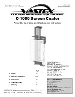
■
Schematic Diagrams
CAUTION
Components indicated by a mark ! in this schematic diagram have the special sig-
nificance in the safety. It is therefore, particularly recommended that the replace-
ment of those parts must be made by exactly the same parts.Must be used with a
specified fuse. Unauthorized substitutions may result in fire or accident.
This projector is isolated from AC line by using the internal converter transformer.
Please pay attention to the following notes in servicing.
1. Do not touch the part on hot side (primary circuit) or both parts on the hot and
cold sides (secondary circuit) at the same time.
2. Do not shorten the circuit between hot and cold sides.
3. The grounding lead must be connected to the ground of the same circuit when
measuring the voltages and waveform.
CAUTION
Fuse of the specified parts number must be used.
Unauthorized substitutions may result in fire or accident.
Schematic Diagrams
Overview
Summary of Contents for D78-5532
Page 2: ...CANON Multimedia Projector LV X4U D78 5532 LV X4E D78 5533 SERVICE SMANUAL ...
Page 9: ...Part 1 General Information ...
Page 26: ...Part 2 Repair Information ...
Page 43: ...Part 3 Adjustment ...
Page 62: ...Part 4 Troubleshooting ...
Page 79: ...Part 4 Troubleshooting 4 17 AN5870SB RGB SYNC SW IC5201 LM4889 Audio Amplifier IC5031 ...
Page 81: ...Part 4 Troubleshooting 4 19 FA5502 P F Control IC621 VPC3230D Video Decoder IC101 ...
Page 84: ...Part 4 Troubleshooting 4 22 TA1370FG Sync Separator Frequency Counter IC5302 ...
Page 85: ...Part 5 Parts Catalog ...
Page 86: ......
Page 94: ......
Page 100: ...Part 6 Electrical Diagrams ...