5
5
5-4
5-4
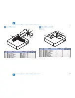
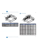
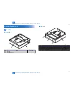
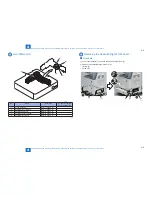
Adjustment > Image position adjustment > Left Non-Image Width
Adjustment > Image position adjustment > Left Non-Image Width
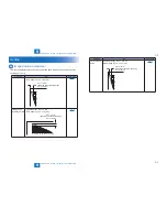
Left Non-Image Width
Service mode > PRINT> PRINT NUMERIC> 034 (Multi-purpose Tray)
Service mode > PRINT> PRINT NUMERIC> 035 (Cassette 1)
Service mode > PRINT> PRINT NUMERIC> 036 (Cassette 2 (option))
Service mode > PRINT> PRINT NUMERIC> 037 (Cassette 3 (option))
Service mode > PRINT> PRINT NUMERIC> 038 (Cassette 4 (option))
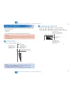
10
8
6
5
4
2
0
1st side of copy: 2.5+/-1.5mm
2nd side of copy: 2.5+/-1.5mm
Image edge
Increase the value.
(an increase of '10' will
increase the non-image
width by 1 mm)
Decrease the value.
(a decrease of '10' will
decrease the non-image
width by 1 mm)
F-5-6
Summary of Contents for Cassette Module-Y1
Page 1: ...6 5 4 3 2 1 Cassette Module Y1 Service Manual Rev 0 ...
Page 6: ... Notes Before it Works Serving Points to Note at Cleaning Safety Precautions ...
Page 8: ...1 1 Product Outline Product Outline Outline Names of Parts ...
Page 10: ...2 2 Technology Technology Basic configuration Controls ...
Page 17: ...3 3 Periodic Servicing Periodic Servicing Periodic Servicing List ...
Page 32: ...5 5 Adjustment Adjustment Outline Image position adjustment ...
Page 36: ...6 6 Installation Installation Installation Installing this Equipment ...
Page 38: ... Service Tools General Circuit Diagram Appendix ...

