2
2
2-2
2-2
Technology > Basic configuration > Paper Path
Technology > Basic configuration > Paper Path
Basic configuration
Parts Configuration
■
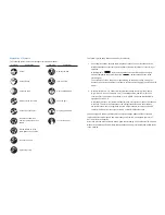
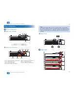
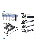
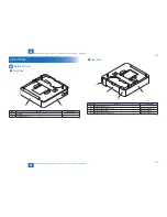
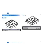
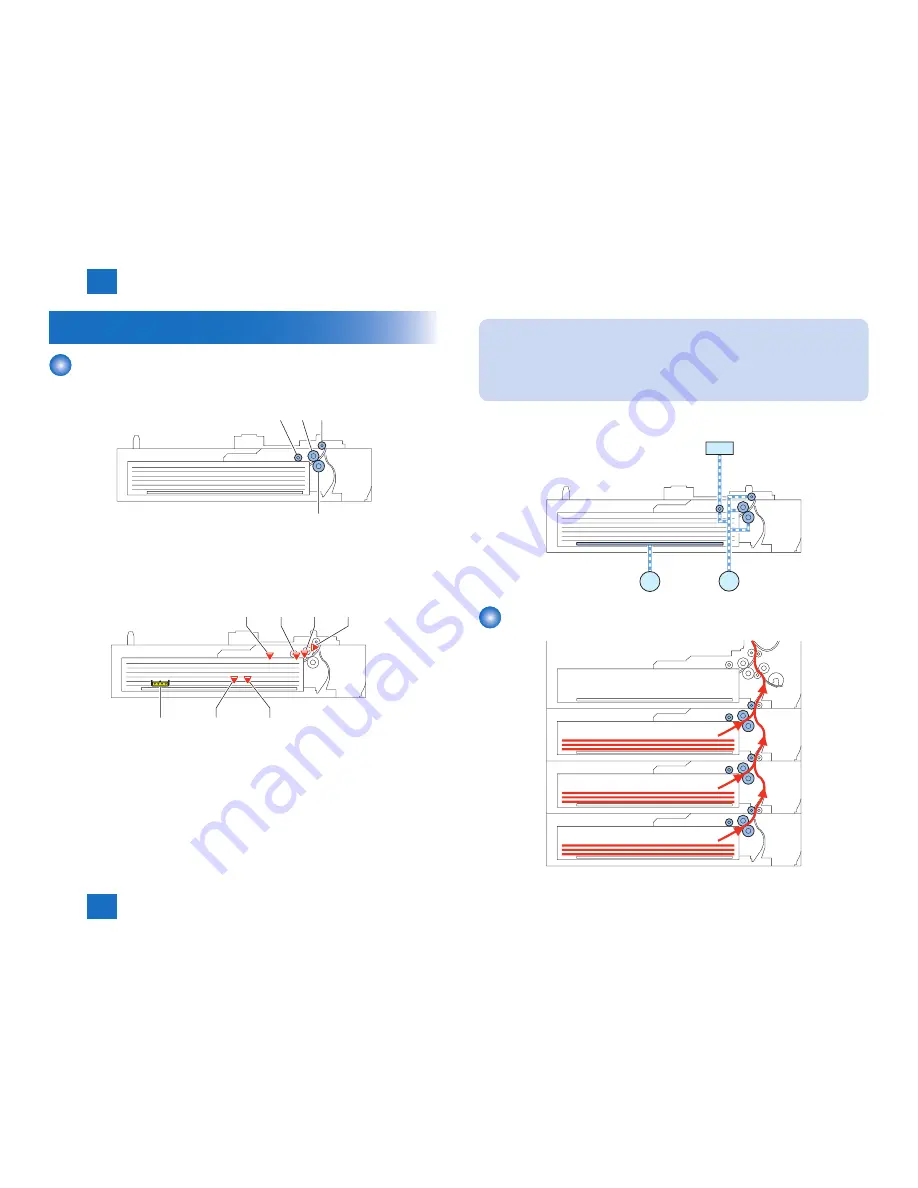
Rollers Layout drawing
[1]
[2]
[3]
[4]
[1]
Pickup Roller
[3]
Separation Roller
[2]
Feed Roller
[4]
Vertical Path Roller
■
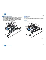
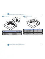
Sensors Layout Drawing
PS103
PS107
PS102
PS101
PS104
PS105
SW101
PS101 Cassette Lifting Plate Detection Sensor
PS105 Cassette Paper Level Sensor B
PS102 Cassette Paper Sensor
PS107 Cassette Pickup Sensor
PS103 Cassette Retry Sensor
SW101 Cassette Size Detection Switch
PS104 Cassette Paper Level Sensor A
F-2-1
F-2-2
NOTE:
Parts numbers of the Cassette 2 are listed. As for parts numbers of the Cassette 3
and Cassette 4, replace the number at the hundreds place of the corresponding parts
number of the Cassette 2 with 2 or 3, respectively. Unless there is a particular difference
in function of each cassette, parts numbers of the Cassette 3 and Cassette 4 are not
mentioned.
■
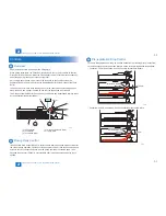
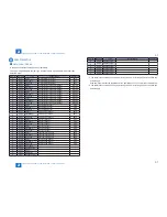
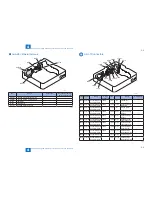
Route of Drive
SL101
M101
M102
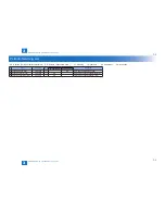
Paper Path
Pickup from Cassette 2
Pickup from Cassette 3
Pickup from Cassette 4
F-2-3
F-2-4
Summary of Contents for Cassette Module-Y1
Page 1: ...6 5 4 3 2 1 Cassette Module Y1 Service Manual Rev 0 ...
Page 6: ... Notes Before it Works Serving Points to Note at Cleaning Safety Precautions ...
Page 8: ...1 1 Product Outline Product Outline Outline Names of Parts ...
Page 10: ...2 2 Technology Technology Basic configuration Controls ...
Page 17: ...3 3 Periodic Servicing Periodic Servicing Periodic Servicing List ...
Page 32: ...5 5 Adjustment Adjustment Outline Image position adjustment ...
Page 36: ...6 6 Installation Installation Installation Installing this Equipment ...
Page 38: ... Service Tools General Circuit Diagram Appendix ...


