2
2
2-3
2-3
Technology > Controls > Pre-registration Stop Control
Technology > Controls > Pre-registration Stop Control
Controls
Overview
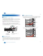
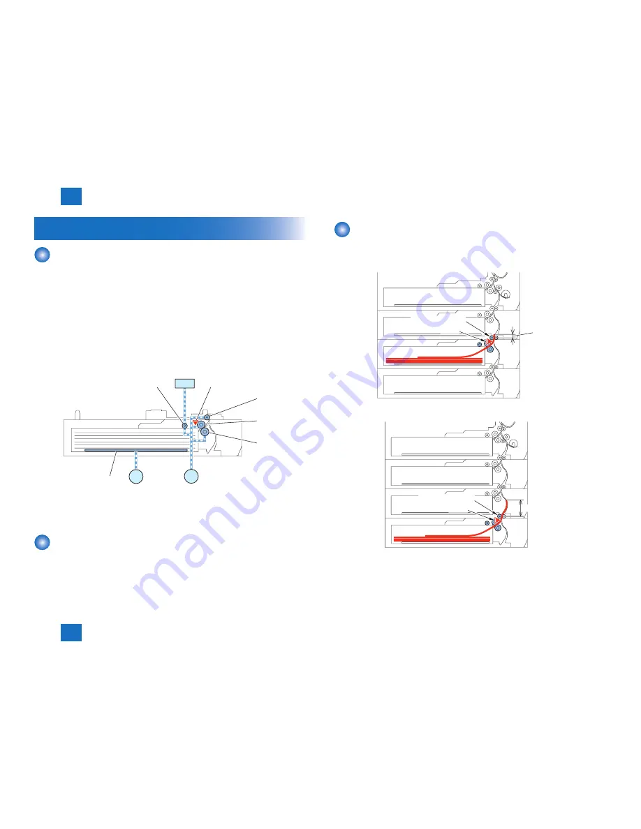
Paper inside a cassette is lifted up by the Lifting Plate.
When pickup takes place, the Cassette Pickup Solenoid (SL101) is turned ON so that the
Pickup Roller is moved down. When the Pickup Roller comes in contact with the surface of
paper, the paper is picked up by rotation of the roller.
Only a single paper picked up is moved to the feed path by the Feed Roller and the
Separation Roller, and moved as far as the Registration Roller by the Pickup Vertical Path
Roller.
If the Pickup Sensor is ON when starting pickup (in the case that the succeeding paper is
also picked up when a paper is picked up and fed), the feed speed is decreased.
The Pickup Vertical Path Roller, Pickup Roller, Feed Roller, and Separation Roller are driven
by the Cassette Pickup Motor (M101).
SL101
M101
M102
[5]
[1]
[2]
[3]
[4]
PS107
[1] Pickup Roller
[4] Pickup Vertical Path Roller
[2] Feed Roller
[5] Lifting Plate
[3] Separation Roller
Pickup Retry Control
If the Cassette Retry Sensor (PS103) is not turned ON within a specified period of time after
the start of pickup operation, operation of the Pickup Motor (M101) and the Cassette Pickup
Solenoid (SL101) is suspended once, and the pickup operation is executed again. If the
Cassette Retry Sensor (PS103) is not turned ON after re-pickup operation, a delay jam is
notified.
F-2-5
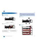
Pre-registration Stop Control
To ensure throughput when picking up from the Cassette 3/4, preceding pickup is executed
so that the second sheet of paper and later are moved to the pre-registration stop position.
• Cassette 3: 7.5mm downstream from the Cassette Vertical Path Roller 3
7.5 mm
Vertical Path Roller 3
PS203
• Cassette 4: 90.5mm downstream from the Cassette Vertical Path Roller 4
Vertical Path Roller 4
PS303
90.5 mm
F-2-6
F-2-7
Summary of Contents for Cassette Module-Y1
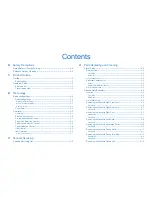
Page 1: ...6 5 4 3 2 1 Cassette Module Y1 Service Manual Rev 0 ...
Page 6: ... Notes Before it Works Serving Points to Note at Cleaning Safety Precautions ...
Page 8: ...1 1 Product Outline Product Outline Outline Names of Parts ...
Page 10: ...2 2 Technology Technology Basic configuration Controls ...
Page 17: ...3 3 Periodic Servicing Periodic Servicing Periodic Servicing List ...
Page 32: ...5 5 Adjustment Adjustment Outline Image position adjustment ...
Page 36: ...6 6 Installation Installation Installation Installing this Equipment ...
Page 38: ... Service Tools General Circuit Diagram Appendix ...


