5
5
5-2
5-2
Adjustment > Outline > Image position adjustment
Adjustment > Outline > Image position adjustment
Outline
Image position adjustment
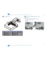
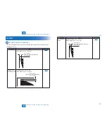
This section describes procedures when adjusting basic image position (image margins,
nonimage area, etc).
Category
Item
Reference
Left Image MarginSingle-sided copy: 2.5 ± 1.5 (mm)
Double-sided copy: 2.5 ± 2.0 (mm)
10
8
6
5
4
2
0
2.5+/-1.5mm
(2nd side of double-sided copy:
2.5+/-2.0mm)
p. 5-3
Leading Edge
Non-Image Width
Single-sided copy: 2.5 ± 1.5 (mm)
Double-sided copy: 2.5 ± 1.5 (mm)
2
5
4 6 8 10 12 14 16 18 20
0
2.5+/-1.5mm
(2nd side of double-sided copy
: 2.5+/-1.5mm)
p. 5-3
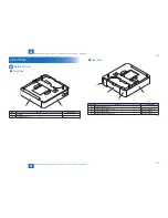
F-5-1
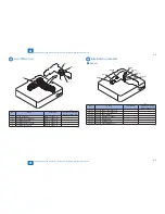
F-5-2
Category
Item
Reference
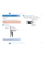
Left Non-Image
Width
Single-sided copy: 2.5 ± 1.5 (mm)
Double-sided copy: 2.5 ± 1.5 (mm)
10
8
6
5
4
2
0
2.5+/-1.5mm
(2nd side of double-sided copy:
2.5+/-1.5mm)
p. 5-4
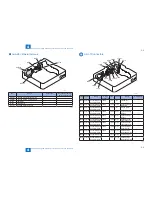
F-5-3
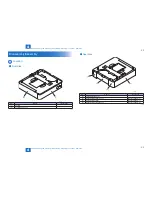
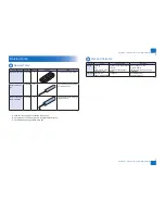
T-5-1
Summary of Contents for Cassette Module-Y1
Page 1: ...6 5 4 3 2 1 Cassette Module Y1 Service Manual Rev 0 ...
Page 6: ... Notes Before it Works Serving Points to Note at Cleaning Safety Precautions ...
Page 8: ...1 1 Product Outline Product Outline Outline Names of Parts ...
Page 10: ...2 2 Technology Technology Basic configuration Controls ...
Page 17: ...3 3 Periodic Servicing Periodic Servicing Periodic Servicing List ...
Page 32: ...5 5 Adjustment Adjustment Outline Image position adjustment ...
Page 36: ...6 6 Installation Installation Installation Installing this Equipment ...
Page 38: ... Service Tools General Circuit Diagram Appendix ...


