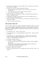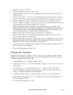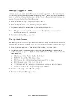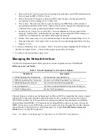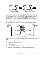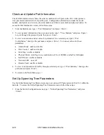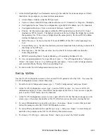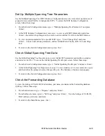
3. Set the optical power meter to the proper wavelength.
4. Wait two or three minutes for the power reading to stabilize, and then read the output power.
5. Subtract out the test cable loss, then record the power level and compare it to the value on the
performance sheet for that particular 9161. Measurement tolerance is +/- 0.5 dBm.
Note: When referencing optical power levels with numerical values less than zero, the reading
closer to zero is the greater value; for example, -17 dBm is greater than -20 dBm.
6. If the reading is incorrect, repeat the measurement with a different test cable. If the power level is
still not within range, call Technical Support.
7. After calculating the link attenuation, subtract that value from the 9161 Tx output value to
determine the power expected at the remote cable end, which is the input power at the remote
receiver.
Measure Receiver Input Power
If you know the link attenuation, skip this section. Otherwise, follow these steps to use the 9161 to
measure the link attenuation.
1. At the local site, connect the fiber link cable to Tx on the 9161.
2. At the remote site, set the optical power meter to the proper wavelength and connect it to the fiber
link cable.
3. Record the optical power level and compare it with the sensitivity level listed on the data sheet
for the link fiber type.
4. Subtract the remote power level from the value for the transmitter output power at the local site.
The result provides the link loss, in dB. This power level must not exceed the limit for Rx
sensitivity listed on the data sheet for the remote unit.
Note: If you cannot determine the Rx sensitivity, contact Canoga Perkins Technical Support
Department for assistance.
Measure Fiber Link Attenuation
Determine and record link attenuation before starting normal link traffic. The attenuation factor
identifies potential problems with links that are on the threshold of receiver limitations.
Measure optical fiber links at the shortest wavelength of operation to determine the limiting factor in
the loss budget. Each device that transmits to an 9161 has a loss budget that is specified by the
manufacturer and recorded on a data sheet provided with the equipment. That loss budget must be
greater than the total of the measured loss of the fiber link and the attenuation of the 9161s.
Use a power meter calibrated for the laser source, then factor in approximately 1 dB for the connector
loss from the patch cables between the 9161 and the local device. (Each fiber connection can
generate 0.5 dB of additional loss.)
4-2
9161 Network Interface Device
Summary of Contents for 9161
Page 1: ...the 9161 Network Interface Device User Manual...
Page 2: ......
Page 4: ......
Page 6: ......
Page 10: ......
Page 41: ...9161 Network Interface Device 3 27 3 22 Blank...
Page 42: ......
Page 50: ......
Page 52: ......
Page 53: ......

