


7
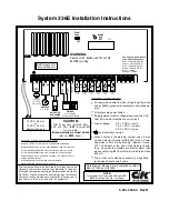
System 236E Installation Instructions
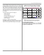
Programming with the LED Keypad
Programming with the LED keypad is a one-step process. Key in
the two-digit address (Command Location) followed by the
desired programming values (program data), then press the [#]
key to store the data. The LED keypad does not display pro-
grammed values. If you are not sure that the correct program-
ming values have been entered, program the Command Location
again.
Option
Location
Loop Restore Type
1D - 22 (3)
Loop Shunting Enable
24 (1 - 6)
Loop Shunt Report Code
15 (2)
Low Battery Report Code
18 (5)
Low Battery Restore Report Code
18 (6)
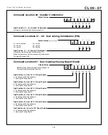
Master Code
01 (1 - 4)
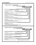
Opening Report Code
16 (2)
Opening/Closing Report Receiver Select
16 (1)
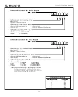
Panic Audible Type
19 (4)
Panic Report Code
19 (1 - 2)
Panic Report Receiver Select
19 (3)
Phone Ring Type
09 (5)
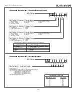
Receiver #1 Message Format
0A (2)
Receiver #1 Phone Number
0C - 0E (1 - 6)
Receiver #1 Receive Format
0A (1)
Receiver #2 Message Format
0A (4)
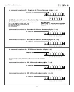
Receiver #2 Phone Number
0F - 11 (1 - 6)
Receiver #2 Receive Format
0A (3)
RPS Enable
09 (3)
RPS Phone Number
12 - 14 (1 - 6)
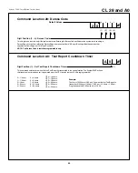
Set Test Report Countdown Timer
A0 (1)
Test Report Code
1A (1 - 2)
Test Report Interval
1A (4)
Test Report Receiver Select
1A (3)
Trouble Report Code
15 (4)
Trouble Restore Code
15 (5)
Unit Status Report Code
17 (1)
User Arming Type
07 (1 - 6)
User Combinations
01 - 06 (1 - 4)
User Code Pager Enable
26 (1 - 6)
Watchdog Reset Report Code
17 (2)
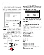
PROGRAMMING THE PANEL
You can program the System 236E from the LED keypad or
remotely using the Commander II software. This manual provides
you with a brief description of each programming option begin-
ning on page 8. Remote Programming information can be found
in the Commander II/Monitor II Operating Manual.
To Start Keypad Programming
Key in the [Installer Combination][*][0][#]. The default installer
combination is:
0 1 2 3 4 5
. On the LED keypad, the ARM,
SERVICE, and AC LED's will flash to indicate programming mode.
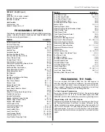
PROGRAMMING OPTIONS
The following is an alphabetical listing of all System 236E programming
options, including Command Locations and Digit Positions. Digit
Positions are inside parentheses ( ).
AC Fail Report Code
18 (3)
AC Line Frequency
08 (6)
AC Restore Report Code
18 (4)
Account Number
0B (1 - 6)
Audible Time
1B (3)
Autohome Enable
1B (6)
Bell Fuse Fail Report Code
18 (1)
Bell Fuse Restore Report Code
18 (2)
Cancel Report Code
15 (3)
Closing Report Code
16 (3)
Combination Command
08 (5)
Completed Programming Report Code
17 (4)
Daily Battery Test Enable
08 (4)
Default Installer Combination
08 (3)
Delay Before Dial Enable
25 (1 - 6)
Delay Before Dial Time
1B (4)
Dial Attempts
09 (2)
Dial Type
09 (6)
Disable Instant/Home Exit Delay
1B (5)
Disable Loop LEDs
08 (1)
Door Chime Enable
23 (1 - 6)
Duress Code
28 (1 - 4)
Duress Report Code
16 (4 - 5)
Entry Delay Time
1B (1)
Event Report Receiver Select
15 (1)
Exit Delay Time
1B (2)
Failed To Communicate Report Code
17 (3)
Faulted Arming Type
08 (2)
Installer Combination
00 (1 - 6)
Keypad Activated Pager Enable
27 (1)
Keypad Pager Report Code
27 (2 - 6)
Keypad RPS Enable
09 (4)
Local System Only
09 (1)
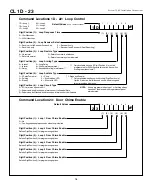
Loop Alarm Report Code
1C (1 - 6)
Loop Arming Type
1D - 22 (4)
Loop Audible Type
1D - 22 (5)
Loop Circuit Type
1D - 22 (6)
Loop Receiver Select
1D - 22 (2)
Loop Response Time
1D - 22 (1)
Loop Restore Reporting Code
15 (5)
Option
Location
Timing
Entry time: 60 seconds, prewarn
Exit time: 30 seconds, prewarn
Bell time: 5 minutes
Unit Control:
Local system: yes
Dynamic battery test: off
DEFAULT VALUES (cont.)


