


2
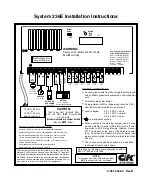
System 236E Installation Instructions
Table of Contents
Subject
Page No.
System 236E Terminal Label
Front Cover
FCC Notice
2
Industry Canada
2
UL Compliance
3
Installation
3
Earth Ground
3
Wiring the Panel
3 - 5
Standby Battery
3
AC Power
4
Audible Output
4
Switched Auxiliary Power
4
Arming Stations
4
Addressing Keypads
5
Loop Inputs
5
Tamper Switch Installation
5 - 6
Telephone Interface
6
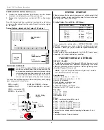
System Start-Up
6
Factory Default Settings
6 - 7
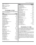
Programming Options (Alphabetical List)
7
Programming the Panel
7
Programming with the LED Keypad
7 - 8
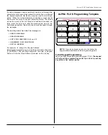
Programming with the Alpha Plus Keypad
8
Programming the Alpha Plus Keypad
8
Keypad Message Programming
8 - 9
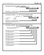
Programming Options (Numerical Order)
10 - 22
Telephone Line Problems
23
Watchdog Indicator
23
Limitations of your alarm system
23
Keypad Operation Command Summary
24
Troubleshooting
25 - 26
Reducing False Alarms
27
Programming Worksheets
29 - 30
FCC Notice
FCC Rules Part 15:
This equipment has been tested and found to comply with Part 15 of the FCC Rules.
These limits are designed to provide reasonable protection against harmful inter-
ference in a residential installation. This equipment generates, uses, and can
radiate radio frequency energy and, if not installed and used in accordance with
the instructions, may cause harmful interference to radio communications. How-
ever, there is no guarantee that interference will not occur in a particular installa-
tion. If this equipment does cause harmful interference to radio or television
reception, which can be determined by turning the equipment off and on, the user
is encouraged to try to correct the interference by one or more of the following
methods:
Reorient or relocate the receiving antenna,
Connect the AC transformer to a different outlet so that the equipment and radio/
television are on different circuits;
Relocate the equipment with respect to the radio/television;
Consult the dealer or an experienced radio/TV technician for help.
FCC Rules Part 68:
This equipment complies with FCC Rules, Part 68. On the outside of this equipment
is a label that contains, among other information, the FCC Registration Number and
Ringer Equivalence Number (REN) for this equipment. If requested, provide this
information to your telephone company.
The REN is useful to determine the quantity of devices you may connect to your
telephone line and still have all of those devices ring when your number is called.
In most, but not all areas, the sum of the REN's of all devices should not exceed five
(5.0). To be certain of the number of devices you may connect to your line, as
determined by the REN, you should call your local telephone company to deter-
mine the maximum REN for your calling area.
FCC Rules Part 68 (cont.)
Should you experience trouble with the telephone lines, disconnect the equipment
from the line to determine the source of the trouble.
If it is determined that the equipment is malfunctioning, discontinue its use until the
malfunction has been corrected. Any repairs or alterations made by the user of this
equipment, or equipment malfunctions, may give the telephone company cause
to request the user to disconnect the equipment. Repairs to this equipment should
be made by an authorized agent of C&K Systems, Inc. Contact tour local alarm
installation company for service.
Should this equipment cause harm to the telephone network, the telephone
company may temporarily discontinue your service. If possible, they will provide
you with advance notice. Otherwise they will notify you as soon as possible. The
telephone company will also advise you of changes in its facilities, equipment,
operations, or procedures which could affect the operation of your equipment,
allowing you the opportunity to maintain uninterrupted service. You will also be
advised of your right to file a complaint with the FCC.
This equipment must not be used on party lines or coin operated phone lines.
Industry Canada
Notice:
The Industry Canada label identifies certain equipment. This certification
means that the equipment meets certain telecommunications network protec-
tive, operational, and safety requirements as prescribed in the appropriate Termi-
nal Equipment Technical Requirements documents. The Department does not
guarantee the equipment will operate to the user's satisfaction.
Before installing this equipment, users should ensure that it is permissible to be
connected to the facilities of the local telecommunications company. The equip-
ment must be installed using an acceptable method of connection. The customer
should be aware that compliance with the above conditions may not prevent the
degredation of service in some situations.
Repairs to certified equipment should be coordinated by a representative desig-
nated by the supplier. Any repairs or alterations made by the user of this equip-
ment, or equipment malfunctions may give the telecommunications company
cause to request the user to disconnect the equipment.
Users should ensure for their own protection that the electrical ground connections
of the power utility, telephone lines, and internal metallic water pipe system, if
present, are connected together. This precaution may be particularly important in
rural areas.
Caution:
Users should not attempt to make such connections themselves, but
should contact the appropriate electric inspection authority, or electrician, as
appropriate.
Notice:
The Ringer Equivalence Number (REN) assigned to each terminal device
provides an indication of the maximum number of terminals allowed to be con-
nected to a telephone interface. The termination on an interface may consist of
any combination of devices subject only to the requirement that the sum of the
Ringer Equivalence Numbers of all devices does not exceed 5.
This Class B digital apparatus meets all requirements of the Canadian Interference-
Causing Equipement Regulations.
Cet appareil numérique de la classe B respecte toutes les exigences du Règlement
sur le matériel brouilleur du Canada.


