background image

Slope adjustment knob

9

8

7

6

5

4

3

2

1

OPT-5405

Quick Reference Guide
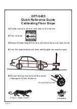
Calibrating Floor Slope

5) 

 Record the bay location and floor slope

 readings for future reference.

1)

  Position aimer in front of, and next to, the vehicle.

2)

  Turn on laser.

3)

  Measure beam height from floor at front wheel and at back wheel.

4)

  Turn the slope adjustment knob until heights are exactly equal.

CAUTION

AVOID  EXPOSURE  -  LASER  LIGHT
IS EMITTED FROM THIS APERTURE

LASER RADIATION

 DO NOT STARE

INTO BEAM

POWER OUTPUT < 1mW

WAVELENGHT: 630-680 nm

CLASS II LASER PRODUCT

Ver050705

Perfect  Night  Vision...

Canbuilt Mfg.

Lift Here

Professional Optical

Headlight Aiming System

Canbuilt Mfg.

Perfect  Night  Vision...

Summary of Contents for OPT-5405

Page 1: ...Model OPT 5405 Canbuilt Mfg Perfect Night Vision Ver 210504 Professional Optical Headlight Aiming System...

Page 2: ...he Standards SAE J599 Aug 1997 and J600 Feb 1993 Aims all headlights including Domestic European andAsian type headlights Laser guided floor slope compensation Simple operation Easily transportable fr...

Page 3: ...1 Laser guided floor slope measurement system not shown COMPONENTS B B A fig 7 pointer system fig 8 Attach the holder to the middle of the aimer head at the tip of the pointer fig 6 Hardware for Point...

Page 4: ...the Aimer Install optical aimer head on mast as shown in fig 2 by pressing trigger lock fig 3 and sliding it down the mast STEP 3 Install the lateral alignment visor fig 5 The narrow slot in the viso...

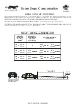
Page 5: ...UIDED FLOOR SLOPE COMPENSATION SYSTEM CAUTION AVOID EXPOSURE LASER LIGHT IS EMITTED FROM THIS APERTURE LASER RADIATION DO NOT STARE INTO BEAM POWER OUTPUT 1mW WAVELENGHT 630 680 nm CLASS II LASER PROD...

Page 6: ...FOR HEADLAMP AIM OR INSPECTION Rotate aimer positioning system pointer to front of aimer Move aimer so that positioning pointer is at center of headlight beam The pointer can be stored as shown with d...

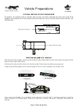
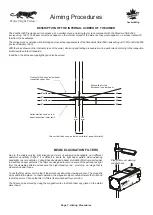
Page 7: ...entering See drawings below Align with center of beam Vehicle Preparations OPTIONAL METHOD OF POSITIONING AIMER POSITIONING AIMER TO VEHICLE With aimer in front of the headlight choose two symmetrical...

Page 8: ...on limits 100 mm 100 mm 100 mm 100 mm 4 4 4 4 8 0 4 4 8 0 Due to the widely varying light intensity and color of automotive headlights and different operators sensitivity to light it is difficult to l...

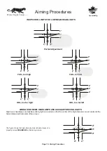
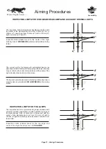
Page 9: ...ical center line of the screen NOTE Headlights centered more than 36 from the ground require beam slope compensation See page 12 for details AIMING LOW BEAM HEADLAMPS INSPECTION LIMITS FOR LOW BEAM HE...

Page 10: ...est down the road and is considered the high intensity zone Many late model headlights have patterns similar to the European beam pattern You should set these headlights using the biased line as shown...

Page 11: ...cedures AIMING HIGH BEAM HEADLAMPS AND AUXILIARY DRIVING LIGHTS High beam headlamps and auxiliary driving lights are aimed so that the center of the high intensity zone is located at the horizontal an...

Page 12: ...h intensity zone at or below the horizontal centerline and the center of the high intensity zone centered on the screen The figure shows shaded area indicates high intensity zone a properly aimed symm...

Page 13: ...48 from the ground must be aimed 2 below the 0 line and headlights mounted 48 54 must be aimed 4 below the 0 line Inspection tolerance is plus or minus 4 7 6 m 25 ft H Nominal Vertical Aim Headlamp ce...

Page 14: ...the illuminated zone is located at the horizontal and biased line European high beams are aimed so that the high intensity zone is centered on the horizontal and vertical center lines 4 0 4 4 4 4 0 4...

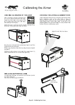
Page 15: ...ODUCT CHECKING CALIBRATION OF THE LASER Calibrating the Aimer fig 29 Adjust the visor line here below Adjust the visor line here Check calibration of the visor by looking through the visor at the late...

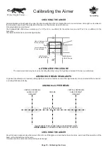
Page 16: ...ights are aimed so that the center of the high intensity zone is located at the horizontal and straight ahead vertically VERTICAL CENTERLINE AHEAD OF LEFT HEADLAMP VERTICAL CENTERLINE AHEAD OF RIGHT H...

Page 17: ...ICAL CENTERLINE AHEAD OF RIGHT HEADLAMP CAR AXIS SCREEN MARKING HEIGHT OF LAMP CENTERS Calibrating the Aimer HIGH INTENSITY ZONE SHADED AREA OF A PROPERLY AIMED LOWER BEAM ON THE AIMING SCREEN IN FRON...

Page 18: ......

Page 19: ...m Canbuilt to purchaser purchaser must pay freight to Canbuilt 7 Proof of purchase must be supplied for all warranty claims 8 Canbuilt shall not be responsible for any incidental or consequential dama...

Page 20: ...NOTES...
Page 21: ...er 3 Measure beam height from floor at front wheel and at back wheel 4 Turn the slope adjustment knob until heights are exactly equal CAUTION AVOID EXPOSURE LASER LIGHT IS EMITTED FROM THIS APERTURE L...

Page 22: ...lope Use pointer to position aimer at center of headlight being aimed With aimer in front of headlight align aimer to vehicle using lateral alignment visor as shown Note For illustrations of high beam...

Reviews: