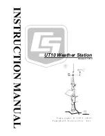
UT10 Weather Station
1.4 Specifications
Required Concrete
Pad Dimensions (see note 1):
61 x 61 x 61 cm (24 x 24 x 24 in)
Crossarm Height (attached to mast)
Standard:
3 m (10 ft)
Maximum (mast fully extended):
3.7 m (~12 ft)
Minimum:
2.7 m (~9 ft)
Pipes Outer Diameter (OD)
Vertical:
2.5 cm (1 in)
Cross
Support:
0.953 cm (0.375 in)
Leg Spacing:
26 cm (10.25 in) between legs (center to center)
Material:
Aluminum
Shipping Weight:
18 kg (40 lb)
Wind Load
Recommendation (see note 2):
110 mph maximum
Notes:
1. The concrete pad requirements assume heavy soil; light, shifting, or sandy
soils require a larger concrete pad.
2. The wind load recommendation assumes proper installation, proper
anchoring, adequate soil, and total instrument projected area of less than 2
square feet. The amount of wind load that this mount can withstand is
affected by quality of anchoring and installation, soil type, and the number,
type, and location of instruments fastened to the UT10.
2. UT10 Tower Installation
2.1 UT10 Tower Installation
The UT10 3-meter tower provides a support structure for mounting the weather
station components. FIGURE 2-1 shows a typical UT10 equipped with an
instrumentation enclosure, meteorological sensors, and a solar panel.
6


