background image

Appendix A.  General Theory of Heat Flux Sensors 

better if the soil conditions are closer to the reference conditions (see 
the sensor specifications) and, in an actual experiment, the expected 
error range will probably be 

±

10%.  

The reference conditions for the calibration are a thermal conductivity 
of 0.8 W/mK and a nominal temperature of 20°C. 

A.2  Extended Theory 

It is obvious that there is the possibility that the sensor itself can 
significantly disturb the phenomenon that it is supposed to measure.  
By adding a sensor to the material under observation, you can add 
additional, and sometimes differing, thermal resistances.  

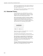
The deflection error, as shown in Figure A-2, represents the effect 
that, as a result of differing resistances, the flow pattern will change, 
especially at the edges of the heat flux sensor.  The order of 
magnitude of this error for strongly different thermal conductivity 
values between the sensor and its environment (for example 0.6 for a 
typical sensor and 0.03 for an insulating wall) is about 40%. 


FIGURE A-2.  Deflection error  

The heat flux is deflected at the edges of the sensor.  As a result, the 
heat flow at the edges is not representative.  

Apart from the sensor thermal resistance, the contact resistance 
between the sensor and surrounding material require special attention.  

The conductivity of air is approximately 0.02W/mK which is ten 
times smaller than that of the heat flux sensor.  It follows, therefore, 
that air gaps can form major contact resistances.  In all cases the 
contact between sensor and surrounding material should be as close 
and as stable as possible, so that it will not influence the 
measurements.  

The aspects of differing thermal properties between sensor and its 
environment can also be dealt with during the measurement using a 
higher accuracy self-calibrating type of heat flux sensor.  


A-2 

Summary of Contents for HFP01

Page 1: ...Model HFP01 Soil Heat Flux Plate Revision 7 12 C o p y r i g h t 2 0 0 2 2 0 1 2 C a m p b e l l S c i e n t i f i c I n c...

Page 2: ......

Page 3: ...emoving reinstalling and shipping defective products to Campbell Campbell will return such products by surface carrier prepaid within the continental United States of America To all other locations Ca...

Page 4: ...g container Campbell Scientific s shipping address is CAMPBELL SCIENTIFIC INC RMA _____ 815 West 1800 North Logan Utah 84321 1784 For all returns the customer must fill out a Statement of Product Clea...

Page 5: ...Wiring 5 6 3 Programming 5 6 4 Soil Heat Flux and Storage 7 7 Maintenance 8 8 References 8 Appendix A General Theory of Heat Flux Sensors A 1 A 1 General Theory A 1 A 2 Extended Theory A 2 Figures 6...

Page 6: ......

Page 7: ...hould be handled as a precision scientific instrument 3 Initial Inspection Upon receipt of the HFP01 inspect the packaging and contents for damage File damage claims with the shipping company The mode...

Page 8: ...he sensor as the HFP01 The sensor s cable can terminate in Pigtails that connect directly to a Campbell Scientific datalogger option PT Connector that attaches to a prewired enclosure option PW Refer...

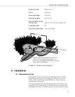
Page 9: ...must be completely inserted into the soil face before the hole is backfilled FIGURE 6 1 Placement of heat flux plates 6 Installation 6 1 Placement in Soil The standard set of sensors for measuring soi...

Page 10: ...t the side with the red label is facing the sky and the side with a blue label facing the soil NOTE In order for the HFP01 to make quality soil heat flux measurements the plate must be in full contact...

Page 11: ...Shield Clear G 6 3 Programming To calculate the calibration multiplier divide 1000 by the nominal calibration sensitivity i e 1000 sensitivity The nominal calibration sensitivity is unique for each HF...

Page 12: ...P01 1 1000 sensitivity 1000 67 1 Const HFP01_CAL_2 14 92 Unique multiplier for HFP01 2 1000 sensitivity 1000 67 0 Variables Energy balance sensors Public shf 2 Dim shf_cal 2 Soil heat flux plate calib...

Page 13: ...n of CR23X Program using the Differential Measurement Instruction The instruction below does not store data in final storage P92 P77 and an output processing instruction are required to store the data...

Page 14: ...lk density and mass basis soil water content can be found by sampling Klute 1986 The volumetric soil water content is measured by the CS616 water content reflectometer A value of 840 J kg 1 K 1 for th...

Page 15: ...and the thermal conductivity of the sensor Using more thermocouples in series will enhance the output signal In Figure A 1 the joints of a copper constantan thermopile are alternatively placed on the...

Page 16: ...r of magnitude of this error for strongly different thermal conductivity values between the sensor and its environment for example 0 6 for a typical sensor and 0 03 for an insulating wall is about 40...

Page 17: ......

Page 18: ...ntific Canada Corp CSC 11564 149th Street NW Edmonton Alberta T5M 1W7 CANADA www campbellsci ca dataloggers campbellsci ca Campbell Scientific Centro Caribe S A CSCC 300 N Cementerio Edificio Breller...

Reviews: