Model HFP01 Soil Heat Flux Plate
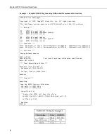
Example 2. Portion of CR10(X) Program using the Single-Ended Measurement Instruction
The instruction below does not store data in final storage. P92,
P77, and an output processing instruction are required to store
the data permanently.
NOTE
01: Volt (SE) (P1)
1: 1
Reps
2: 2
7.5 mV Slow Range
;CR510 (7.5 mV);CR23X (10 mV); 21X, CR7 (5 mV)
3: 5
SE
Channel
;White wire (SE 5), Green wire (AG)
4: 1
Loc [ HFP01 ]
5: 14.90
Mult
;Enter Calibration
6: 0
Offset
TABLE 6-4. Wiring for Example 3
Description
Color
CR23X
Signal White
9H
Signal Reference
Green
9L
Shield Clear
Example 3. Portion of CR23X Program using the Differential Measurement Instruction
The instruction below does not store data in final storage. P92,
P77, and an output processing instruction are required to store
the data permanently.
NOTE
;Measure the HFP01 Soil Heat Flux plate.
;
01: Volt (Diff) (P2)
1: 1
Reps
2: 21
10 mV, 60 Hz Reject, Slow Range
;CR510, CR10(X) (7.5 mV); 21X, CR7 (5 mV)
3: 9
DIFF
Channel
;White wire (9H); Green wire (9L)
4: 1
Loc [ HFP01 ]
5: 14.90
Mult
;Enter Calibration
6: 0
Offset
6.4 Soil Heat Flux and Storage
The soil heat flux at the surface is calculated by adding the measured flux at a
fixed depth, d, to the energy stored in the layer above the heat flux plates. The
specific heat of the soil and the change in soil temperature,
Δ
T
s
, over the
output interval, t, are required to calculate the stored energy.
7


