Appendix A. General Theory of Heat
Flux Sensors
This Appendix discusses the general theory and characteristics of heat flux sensors
similar to the HFP01.
A.1 General Theory
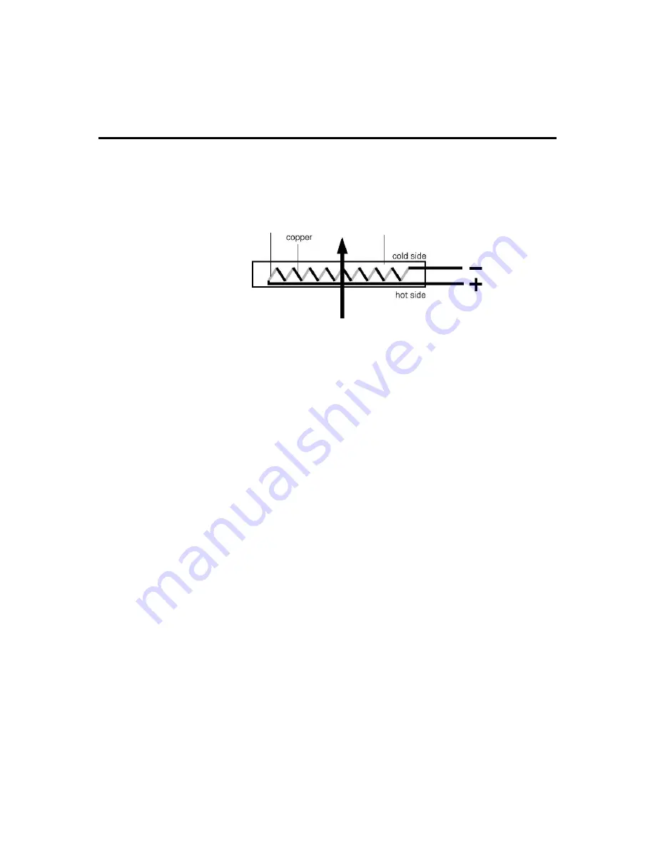
constantan
filler
FIGURE A-1. General characteristics of a heat flux sensor
When heat is flowing through the sensor in the indicated direction, the
filling material will act as a thermal resistance. Consequently the heat
flow,
ϕ
, will follow a temperature gradient across the sensor, flowing
from the hot to the cold side. Most heat flux sensors are based on a
thermopile—a number of thermocouples connected in series. A single
thermocouple will generate an output voltage that is proportional to
the temperature difference between the joints (copper-constantan and
constantan-copper). Provided that errors are avoided, the temperature
difference is proportional to the heat flux—depending only on the
thickness and the thermal conductivity of the sensor. Using more
thermocouples in series will enhance the output signal. In Figure A-1,
the joints of a copper-constantan thermopile are alternatively placed
on the hot and the cold side of the sensor.
The thermopile is embedded in a filling material, usually a plastic.
Each individual sensor will have its own sensitivity, E
sen
, usually
expressed in Volts output, V
sen
, per Watt per square metre heat flux,
ϕ
.
The flux is calculated:
ϕ
=V
sen
/E
sen
The sensitivity is determined by the manufacturer, and is found on the
calibration certificate that is supplied with each sensor.
When used for measuring soil heat flux, heat flux sensors such as the
HFP01 reach a limited level of accuracy. This has to do with the fact
that thermal parameters of soil are constantly changing (soil moisture
content) and with the fact that the ambient temperature is not fixed. A
realistic estimate of the error range is
±
20% over a thermal
conductivity range from 0.1 to 1.7 W/mK (dry sand to water-saturated
sand) across the temperature range of -30° to +70°C. The accuracy is
A-1


