Section 2. Hardware Installation
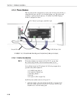
Temp/RH with
Cap Removed
FIGURE 2.4-3. Temperature/Relative Humidity Sensor
without Yellow Protective Cap
3.
Insert the temperature/relative humidity into the gill radiation shield until
it stops or a “click” is heard.
4.
Attach the gill radiation shield to the underside of the crossarm using the
two Phillips screws from step 1.
2.4.4 034B Wind Sensor (Wind Sensor Option –MW)
1.
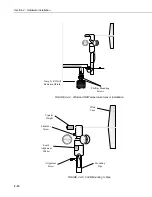
Install the 034B Wind Sensor as shown in Figure 2.4-4 after the sensor
arm is securely installed.
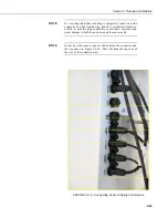
Plugging this sensor into the connector marked “SDI
12” can result in damaging this sensor, the main
enclosure connector board, or both.
WARNING
2-11
Summary of Contents for ET107
Page 8: ...ET107 Weather Station Table of Contents vi This is a blank page...
Page 68: ...Section 3 ET Software 3 2 This is a blank page...
Page 86: ...Section 4 Maintenance Troubleshooting and Schematics 4 18...
Page 101: ...Appendix C Exploded Views C 1 Enclosure C 1...
Page 102: ...Appendix C Exploded Views C 2 Crossarm C 2...
Page 109: ......

