Section 2. Hardware Installation
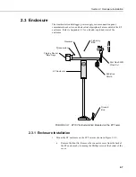
b. Loosen the mounting bracket bolts on the back of the enclosure wide
enough to slide over the pole. Slide the enclosure over the pole.
Position the enclosure so it faces east for northern latitudes or west
for southern latitudes. The top of the enclosure should be 2 – 2.5 cm
(3/4” to 1”) above the top of the pole (see Figure 2.3-2).
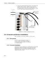
2 – 2.5 cm
Power Cable
(if using AC
transformer)
Ground
Wire
COM Cable
(if using phone or
short-haul modem)
FIGURE 2.3-2. Enclosure Spacing Above Pole
2.4 Crossarm and Sensor Installation
Refer to Appendix C.2 for a labeled, exploded view of the crossarm.
2.4.1 Components
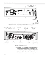
(1) ET107 Crossarm with Sensors (see Figure 2.3-1)
(1) Met One 034B or Gill WindSonic Wind Sensor
(1) White Mounting Shaft for 034B or Gill WindSonic
(1) Gill Radiation Shield
2.4.2 Crossarm Installation
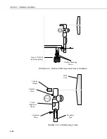
Adjust the bolts at the base of the pole to vertically level the top section of the
mounting pole. Install the ET107 Sensor Arm after the ET Enclosure is
mounted on the ET Tower. You may need to temporarily remove the
communications option. Mount the sensor arm as shown in Figure 2.4-1
without the wind sensor attached.
2-8
Summary of Contents for ET107
Page 8: ...ET107 Weather Station Table of Contents vi This is a blank page...
Page 68: ...Section 3 ET Software 3 2 This is a blank page...
Page 86: ...Section 4 Maintenance Troubleshooting and Schematics 4 18...
Page 101: ...Appendix C Exploded Views C 1 Enclosure C 1...
Page 102: ...Appendix C Exploded Views C 2 Crossarm C 2...
Page 109: ......

