background image

Section 2.  Hardware Installation 

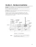
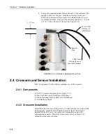
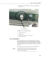
Screws 
(4)


FIGURE 2.4-1.  ET107 Sensor Arm Mounting 

1)  Remove the front lid and the protective connector cover from the back of 

the ET enclosure by loosening the one Phillips screw at the bottom of the 
cover. 

2)  Place the sensor arm on top of the enclosure, lining up the four threaded 

holes on the under side of the arm with the four holes in the top of the 
enclosure.  Attach the arm to the enclosure by inserting and tightening 
four Phillips head screws.  Adjust the position of the ET Enclosure so that 
the crossarm is oriented along a due north to due south axis with the rain 
gage and solar radiation sensor (pyranometer) on the south side for 
northern latitudes and the reverse for southern latitudes. 

2-9 

Summary of Contents for ET107

Page 1: ...ET107 Weather Station Revision 5 09 C o p y r i g h t 1 9 9 3 2 0 0 9 C a m p b e l l S c i e n t i f i c I n c...

Page 2: ...ries served by Campbell Scientific Inc directly Affiliate companies handle repairs for customers within their territories Please visit www campbellsci com to determine which Campbell Scientific compan...

Page 3: ...Vane Orientation 1 6 1 5 1 NSSDC CGM Service 1 7 2 Hardware Installation 2 1 2 1 Base Foundation 2 2 2 1 1 Supplied Components 2 2 2 1 2 Installation 2 2 2 1 3 AC Power Installation 2 4 2 2 Tower Pol...

Page 4: ...43 2 8 Battery Installation 2 45 2 9 Restraining Cables and Sealing Desiccating Enclosure 2 46 2 9 1 Restraining Cables 2 46 2 9 2 Sealing and Desiccating the Enclosure 2 47 3 ET Software 3 1 4 Maint...

Page 5: ...Are Added to 0 to Get True North 1 9 2 1 1 ET Tower Installation 2 1 2 1 2 ET Tower Base Installation 2 3 2 1 3 Cut Away View Shows Anchor Bolt and Conduit Placement in Cement Pad 2 3 2 2 1 Transparen...

Page 6: ...2 40 2 5 16 A Base Radio Installed in an Office 2 40 2 6 1 Lightning Rod Bracket Installation 2 41 2 6 2 Grounding to Lightning Rod Clamp 2 42 2 7 1 Solar Panel Mounting and Cabling 2 43 2 7 2 Side Vi...

Page 7: ...e Up B 6 B 2 4 Enclosure Mounted on ET107 Pole B 7 B 2 5 Enclosure Locking Mechanism B 8 B 2 6 Mounted Solar Panel B 9 B 2 7 Procedure for installing and connecting battery B 11 Tables 4 1 1 CR1000 Li...

Page 8: ...ET107 Weather Station Table of Contents vi This is a blank page...

Page 9: ...1 WMO 1983 2 and AASC 1985 3 publications 1 1 1 Wind Speed and Direction Wind sensors should be located over open level terrain and at a distance of at least ten times EPA the height of any nearby bui...

Page 10: ...urfaces and sources of artificial radiation should be avoided 1 1 4 Soil Temperature The measurement site for soil temperature should be at least 1 m2 10 76 ft2 and typical of the surface of interest...

Page 11: ...wn in Figure 1 2 1A Cut the tape along the edge of the lower flap first See Figure 1 2 1A Cut the tape around the remaining flaps BUT only cut one layer deep Lift up the cardboard flaps exposing the t...

Page 12: ...tape box shut if transporting entire station to another site If at the main site remove any communication components that are installed at the calling computer Repackage remaining components for tran...

Page 13: ...tion are listed below 1 3 1 Tools for Pole Installation ET Pole Shovel Rake Open end wrenches 3 8 7 16 2 9 16 Magnetic compass 6 Step ladder Tape measure 12 to 20 Claw hammer Level 24 to 36 Hand saw M...

Page 14: ...al cable with a minimum of 2 twisted pairs with shield minimum 5 conductors total to travel from the weather station to the central computer junction box Direct burial armored cable may be required fo...

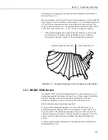
Page 15: ...E 8 E 6 E 4 E 2 E 0 2 W 4 W 6 W 8 W 10 W 14 W 12 W 16 W 18 W 20 W 20 E FIGURE 1 5 1 Magnetic Declination for the Contiguous United States 1 5 1 NSSDC CGM Service The NSSDC CGM Corrected Geomagnetic S...

Page 16: ...modeling of the geomagnetic field parameters Results of GEO CGM calculations Geocentric CGM L value IGRF Magnetic Field Oval Azimuth MLTMN Lat Long Lat Long Re H Nt D deg Z nT angles N S E W in UT Sta...

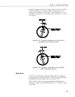
Page 17: ...2 degrees FIGURE 1 5 2 Declination Angles East of True North Are Subtracted From 0 to Get True North FIGURE 1 5 3 Declination Angles West of True North Are Added to 0 to Get True North References 1 E...

Page 18: ...can Association of State Climatologists Height and Exposure Standards for Sensors on Automated Weather Stations v 9 No 4 October 1985 4 EPA 1989 Quality Assurance Handbook for Air Pollution Measuremen...

Page 19: ...riate time Once attached they cannot be detached The ET Tower provides a support structure for mounting the ET107 weather station components Figure 2 1 1 shows a typical ET Tower installation option T...

Page 20: ...nough in diameter to insert one end of the conduit Make certain the cavity points in the direction from which power and communications cables will come For example the cavity will point towards a valv...

Page 21: ...TOP VIEW ANCHOR BOLT FORM FORM WIRE CEMENT PAD SMALL CAVITY 24 24 24 TEMPLATE 2 NORTH FORM WIRE FIGURE 2 1 2 ET Tower Base Installation Conduit Anchor Bolt FIGURE 2 1 3 Cut Away View Shows Anchor Bol...

Page 22: ...e See Figure 2 4 17 The splice and wire nut must be completely immersed into the silicon gel inside the splice tube to be waterproof NOTE 2 2 Tower Pole 2 2 1 Supplied Components 1 Upper Tower Section...

Page 23: ...RF options will not have power or communication cables NOTE 5 Place the white tower cap over the tower end 6 Raise the tower on a still day Place a washer on top of the two nuts on each foundation bo...

Page 24: ...nd Be careful not to damage the clamp with the hammer 2 Taking care not to damage power or communications lines drive the ground rod close to the foundation using a fence post driver or sledge hammer...

Page 25: ...enclosure Logan Utah MADE IN USA Lightning Rod Tipping Bucket Rain Gage Pyranometer Crossarm Radiation Shield Met One 034B Wind Set ET Enclosure Ground Rod FIGURE 2 3 1 ET107 Instrumentation Mounted o...

Page 26: ...3 2 Enclosure Spacing Above Pole 2 4 Crossarm and Sensor Installation Refer to Appendix C 2 for a labeled exploded view of the crossarm 2 4 1 Components 1 ET107 Crossarm with Sensors see Figure 2 3 1...

Page 27: ...of the enclosure lining up the four threaded holes on the under side of the arm with the four holes in the top of the enclosure Attach the arm to the enclosure by inserting and tightening four Phillip...

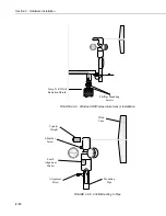
Page 28: ...ove the two Phillips screws taped underneath the crossarm 2 Remove the yellow shipping cap from off the end of the temperature relative humidity sensor See Figures 2 4 2 and 2 4 3 Remove Yellow Cap FI...

Page 29: ...ops or a click is heard 4 Attach the gill radiation shield to the underside of the crossarm using the two Phillips screws from step 1 2 4 4 034B Wind Sensor Wind Sensor Option MW 1 Install the 034B Wi...

Page 30: ...Temperature Sensor Installation UTION ENTIOMETER ENT 5mA FACE SOUTH FIGURE 2 4 5 034B Mounting to Pipe Shoulder Screw South Alignment Sticker Temp RH Gill Radiation Shield Phillips Mounting Screws Win...

Page 31: ...be pointing due south Make sure the sensor cable is not being pinched by the U bolt Tighten up the U bolt to hold the sensor firmly Plug the cable into the mating connector on the sensor Plug must be...

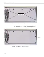
Page 32: ...dware Installation Loosen Screws FIGURE 2 4 6 Screws that Secure the Electronics Cover 4 Remove the electronics cover to expose the PCB see Figure 2 4 7 Lift Here FIGURE 2 4 7 Removal of the Electroni...

Page 33: ...lectronics cover 7 Tighten screws 8 Reattach 10588 ribbon cable to the CS I O port 9 Replace enclosure cover 2 4 5 2 Attachment to Sensor Arm 1 Remove the three Phillips screws from the end of the whi...

Page 34: ...de the connector and cable up through the center of the mounting shaft Plug the cable into the Gill WindSonic sensor The connector has a key and needs to be pushed in then rotated clockwise to lock it...

Page 35: ...bolt 2 4 6 Rain Gage For accurate measurements the rain gage needs to be installed so it is horizontally level A bubble level is situated on the bottom of the inside of the rain gage To see the bubble...

Page 36: ...d in Figure 2 4 12 Adjust the three leveling screws until the bubble level indicates plumb Remove the red or green shipping cap from the pyranometer See Figure 2 4 13 Leveling Screws FIGURE 2 4 12 Pyr...

Page 37: ...sible connectors on the back of the ET107 station Check the programming software for correct station connection The cable used with the soil temperature sensor is waterproof but not armored Route cabl...

Page 38: ...are Installation Loosen Screws FIGURE 2 4 14 Screws that Secure the Electronics Cover 4 Remove the electronics cover to expose the PCB see Figure 2 4 15 Lift Here FIGURE 2 4 15 Removal of the Electron...

Page 39: ...jacket The jacket is waterproof but NOT cut proof The recommended method is to bury conduit from the weather station to the soil water content measurement site and route the sensor cable through the c...

Page 40: ...th the sensor labeling on the back of the enclosure The 034B Wind Sensor plugs into the connector labeled WS WD Plugging this sensor in the connector labeled SDI 12 may damage the sensor and or the ma...

Page 41: ...ockwise Failure to seat the plug completely could cause corrosion and water damage to both the enclosure and the sensor cable NOTE Notice how the sensor caps are slid between the connector and the one...

Page 42: ...t CE if using a Windows CE based handheld with connector cable 2 5 Communication Peripherals Only one communication kit can be mounted inside the ET enclosure Communication kits ordered with the ET En...

Page 43: ...tion Utility DevConfig and connect directly to the station to change the CR1000 configuration DevConfig is included with LoggerNet and can be obtained at no charge from our website NOTE Connects with...

Page 44: ...ons battery not shown 2 5 2 1 Internal Installation If the phone modem was ordered with the ET107 you can skip this section and go directly to the External Installation section NOTE For installation i...

Page 45: ...turned revolution clockwise Failure to seat the plug completely could cause corrosion and water damage to both the enclosure and the sensor cable NOTE 2 Splice the labeled Tip and Ring lines of the p...

Page 46: ...ection 2 5 3 1 Internal Installation If the short haul modem was ordered with the ET107 you can skip this section and go directly to the External Installation section NOTE For installation inside the...

Page 47: ...n the lever arm Pressing too hard on the lever arm can cause it to break WARNING 2 5 3 2 External Installation The following short haul kit components see Figure 2 5 1 are used to make the external co...

Page 48: ...le tie Connect the Rad to the PC s serial port with the 9 to 25 pin serial cable 4 Route the user supplied cable from the remote splice to the surge protector Connect it and the 5 foot patch cable to...

Page 49: ...ith a 10 watt panel would need at least 3 hours of sunlight every day to keep the battery charged Recommendation here would be to decrease the power output of the radios or add a PS24 power supply and...

Page 50: ...the station down by flipping the PS100 power switch to Off before installing any communication option Remember to flip the switch back to On after enclosure installation is completed NOTE 1 Mount the...

Page 51: ...366 5 16 Stainless Steel Lock Washers 4 17592 14 5 Inch Black UV Resistant Wire Ties The 14221 3 dBd Omni or the 14205 6 dBd Yagi Directional Antenna with Type N Female Connector should have been orde...

Page 52: ...Section 2 Hardware Installation FIGURE 2 5 7 Loosely Wire Tie Antenna Cable FIGURE 2 5 8 Loosely Drape Antenna Cable over Back of Enclosure 2 34...

Page 53: ...of an omni directional antenna should not be higher than the top of the lightning rod Slide the U bolt behind the pole and through the oval notches on the adjustable angle mounting bracket see Figure...

Page 54: ...to the adjustable angle mount bracket by inserting the ends of the bracket through the quarter circle notches Put a flat washer lock washer and a silicon bronze nut in that order on the ends of the s...

Page 55: ...erference is a concern then align the tines on the two Yagi antennas horizontally instead of vertically This will put the signal out of phase with other antennas that are aligned vertically Tighten th...

Page 56: ...o the antenna as shown in Figure 2 5 13 Leave a little slack on the cable between the wire tie and the antenna connector so as not to stress the connector cable connection vii Make sure there is a loo...

Page 57: ...r to comply with the FCC RF exposure requirements the RF450 series may be used only with approved antennas that have been tested with this radio and a minimum separation distance of 8 inches 20 cm mus...

Page 58: ...Section 2 Hardware Installation FIGURE 2 5 15 Base RF450 Installation FIGURE 2 5 16 A Base Radio Installed in an Office 2 40...

Page 59: ...rod clamp to the top of the pole see Figure 2 6 1 Position the clamp so it won t interfere with the connector cover FIGURE 2 6 1 Lightning Rod Bracket Installation 2 Strip 2 54 cm 1 from the top of t...

Page 60: ...nd into the enclosure ground lug located at the top back of the enclosure Put the other end in the same clamp opening as the main grounding wire and tighten down the screw see Figure 2 6 2 4 Insert th...

Page 61: ...n Figure 2 7 1 Mount the solar panel to the tower so it faces south northern hemisphere Position it as high off the ground as practical ensuring it cannot interfere with air flow or sunlight around th...

Page 62: ...determining the tilt angle loosen the two bolts that attach the mounting bracket to the panel Adjust the angle then tighten the bolts Secure the lead wire to the mast using wire ties as show in Figur...

Page 63: ...y lead into the connector labeled BATTERY Internal 12V 7 Amp Hour Put the cover back on the PS100 and latch it in place Do not switch the power supply to on until AC or solar power has been connected...

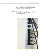
Page 64: ...re tie at this time See Figure 2 9 1 Wire Tie Harness FIGURE 2 9 1 Cabling Strapped to Wire Tie Harness 2 Replace the connector cover The tab at the top of the connector cover slides into the opening...

Page 65: ...of condensation on the instrumentation Desiccant should be changed when the internal ET Enclosure humidity sensor measures 50 or higher Install the desiccant as shown in Figure 2 9 3 Keep unused desi...

Page 66: ...Section 2 Hardware Installation 2 Be sure to close the enclosure hasp securely A padlock may be used on the latch for extra security Desiccant FIGURE 2 9 3 Desiccant Installation 2 48...

Page 67: ...and collect data PC200W software cannot be used to communicate with stations on a phone modem Both packages can be downloaded from Campbell Scientific s website www campbellsci com VisualWeather vers...

Page 68: ...Section 3 ET Software 3 2 This is a blank page...

Page 69: ...ural damage proper alignment and for level plumb 4 1 2 Power Supply 4 1 2 1 Batteries Rechargeable power supplies should be connected to an AC transformer or unregulated solar panel at all times The P...

Page 70: ...arefully when cleaning Be careful not to scratch the surface of the sensor CAUTION Do a visual audio inspection of the 034B ET s anemometer at low wind speeds Worn bearings can cause the wind cups to...

Page 71: ...in the field Replace 034B ET wind speed anemometer reed switch item 13764 if needed To send the sensor to Campbell Scientific for reed switch replacement call for Return Material Authorization number...

Page 72: ...t be calibrated in the field Some users recommend calibrating this sensor on a yearly basis 4 5 years Check sensor cables as well as all other cables for cracking deterioration proper routing and stra...

Page 73: ...ic to have Campbell Scientific replace the battery when voltage is approximately 2 7 V If the lithium cell is removed or allowed to discharge below the safe level the ET107 will still operate correctl...

Page 74: ...osure E Cycle the power to the datalogger by switching the PS100 power supply to OFF then to ON or disconnecting and reconnecting the battery plug Keypad should power up and the Campbell Scientific lo...

Page 75: ...place see Figure 2 4 18 Check connectors for any corrosion on pins C If Short Cut or VisualWeather is used to create the station program double check the wiring diagram to see if it matches the physi...

Page 76: ...ect bulkhead connector If CRBasic is used to create the station program verify channel assignments and multipliers Datalogger program may need to be changed 4 2 6 Communication Problems when using an...

Page 77: ...epeater and Slave linked to Master Slave sending data to Master Solid bright red OR Solid green RCV data Solid dim red Intermittent flashing red Solid green Intermittent flashing red Solid bright red...

Page 78: ...d but no response from datalogger 1 Check SC12 cable on the datalogger s CS I O port 2 Check SDC address in RF450 3 Check SDC address in datalogger 4 Check the baud rate of all RF450s they should be t...

Page 79: ...cient samples possible path obstruction 8 NVM error Nonvolatile Memory checksum failed 9 ROM error Read Only Memory checksum failed 10 Maximum Gain Questionable wind measurements 4 3 Schematics of Con...

Page 80: ...hrough 4 3 7 for help in troubleshooting Temp RH 1 2 3 4 5 6 Air Temperature and Relative Humidity Sensor Connector Pin Datalogger Relative Humidity 0 1VDC Air Temperature 0 1VDC 12V Switched Supply N...

Page 81: ...6 1 2 3 4 5 6 WS WD FIGURE 4 3 2 Schematic of 034B LC Wind Speed and Direction Probe and Connector WS WD 1 Connector Pin Temp Sonic RS232 Recieve Excitation Temperature Signal Return Datalogger Ground...

Page 82: ...ematics Solar Radiation Sensor 450 650 OHMS Connector Pin Datalogger 1 3 2 Not Used Not Used Not Used 3 H 3 L G Shield 4 5 6 1 2 3 4 5 6 Solar Radiation FIGURE 4 3 4 Schematic of CS305 ET Solar Radiat...

Page 83: ...cs 1 Not Used Connector Pin Magnetically Activated Reed Switch Tipping Rain Bucket Not Used Not Used Ground Pulse Datalogger Shield 2 4 3 P2 G G 5 6 1 2 3 4 5 6 Rain Precip FIGURE 4 3 5 Schematic of T...

Page 84: ...und 2 3 4 12V EX3 4L 4H G C7 5 6 1 2 3 4 5 6 TEMP CS616 FIGURE 4 3 6 Schematic of 107 LC or 108 LC Temperature Probe or CS616 LC Soil Volumetric Water Content Sensor and Connector Temp CS616 1 Connect...

Page 85: ...Power FIGURE 4 3 8 Schematic of Solar Panel and Connector Power 4 3 3 Communication Modems Schematics 1 Connector Pin Short Haul or Phone Modem RJ11 Phone Jack Pin 3 RJ11 Phone Jack Pin 2 XMT Termina...

Page 86: ...Section 4 Maintenance Troubleshooting and Schematics 4 18...

Page 87: ...A ET107 Maintenance Log Station Installation Date __________________ CLEAN INSPECT RAIN GAGE SENSOR Recommended Weekly CLEAN INSPECT RAIN GAGE SENSOR Recommended Weekly Date OK Comments Date OK Comme...

Page 88: ...arterly Date OK Comments REPLACE WIND SPEED BEARINGS AND REED SWITCH Recommended Yearly Date OK Comments REPLACE RH CHIP P N 9598 IN THE HMP50 ET TEMP RH SENSOR Recommended Yearly Date OK Comments REP...

Page 89: ...The PS24 consists of a 24 Ahr rechargeable battery CH100 regulator and a 10 x 12 environmental enclosure see Figures B 1 1 through B 1 3 The battery should be recharged via ac power or solar power An...

Page 90: ...Appendix B PS24 24 Ahr Power Supply and 10 x 12 inch Enclosure FIGURE B 1 2 24 Ahr Battery and Battery Cable B 2...

Page 91: ...TYPE I II REACTIVATION TIME IN BAG 16 HOURS AT 250 F DESICCANT ACTIVATED BAGGED FOR CONTENTS 4 UNITS PACKAGE USE AND STATIC DEHUMIDIFICATION DO NOT EAT UNITED DESICCANTS GATES 101CHRISTINE BELEN NOW M...

Page 92: ...structed to do so CAUTION 1 Place the top enclosure bracket on the pole at approximately 40 inches above the bottom of the pole The bracket should be installed with the hook side up and facing north 2...

Page 93: ...below the top clamp This clamp is installed with the hook side down The bracket might have to be moved a little to accept the enclosure bracketing so don t tighten the bracket yet Figure B 2 2 shows...

Page 94: ...Appendix B PS24 24 Ahr Power Supply and 10 x 12 inch Enclosure 4 Hook the enclosure on the top bracket as shown in Figure B 2 3 FIGURE B 2 3 Top Clamp Hook Side Up B 6...

Page 95: ...racket should slide between the top lip of the bottom strut mount bracket and the notch directly below Move the bottom bracket if necessary then bolt the bottom bracket down see Figure B 2 4 Do NOT ov...

Page 96: ...lips screw underneath the mechanism and slide it to the left Once in place put a small wire tie in the hole to the right of the locking mechanism see Figure B 2 5 To remove the enclosure from the brac...

Page 97: ...anel 8 Throw a blanket or box over the solar panel to prevent any voltage output 9 Route the solar panel cable and power cable coming from the main ET107 enclosure into the conduit at the bottom of th...

Page 98: ...rminal block NOTE 11 Remove the blanket or box from the solar panel once it s wired in place 12 Wire the power cable coming from the ET107 station as follows Power Cable from ET107 to CH100 Red 12 Bla...

Page 99: ...p of ground wire was sent with the station Use it to ground the enclosure to the grounding rod system The external ground lug is mounted on the bottom left hand corner of the 10 x 12 enclosure 15 Flip...

Page 100: ...17 Put both bags of desiccant inside of the enclosure 18 Stick the humidity indicator card on a wall inside of the enclosure Pink on the humidity indicator card means it s time to change the desiccant...

Page 101: ...Appendix C Exploded Views C 1 Enclosure C 1...

Page 102: ...Appendix C Exploded Views C 2 Crossarm C 2...

Page 103: ...sable_flag As Boolean Dim checksum_flg As Boolean Dim one Units one samples Public diag Units diag unitless CONNECTOR RAIN PRECIP TE525 ET Public Rain_mm Public Rain 24 Public Rain24Ttl Alias Rain 1 R...

Page 104: ...mum 1 HeatIndxC FP2 False False EndTable DataTable STATS TRUE 168 DataInterval 0 60 Min 10 Totalize 1 one IEEE4 disable_flag FieldNames n_TOT Totalize 1 one IEEE4 diag 1 FieldNames diag_1_TOT Totalize...

Page 105: ...pF AirTempC 1 8 32 VoltDiff SlrRad_W 1 mV7_5 3 true 0 _60Hz 200 0 If SlrRad_W 0 Then SlrRad_W 0 DewPoint DewPntC AirTempC RelHum If DewPntC AirTempC OR DewPntC NAN Then DewPntC AirTempC Wind chill cal...

Page 106: ...CONNECTOR RAIN PRECIP TE525 ET Public Rain_mm Public Rain 24 Public Rain24Ttl Alias Rain 1 RainHrTtl CONNECTOR TEMP RH HMP50 ET Public AirTempC Public AirTempF Public RelHum CONNECTOR Solar Radiation...

Page 107: ...Next n Scan 5 Sec 3 0 BattVolt Status Battery 1 1 LogrTmpC Status PanelTemp 1 1 WatchDog Status WatchdogErrors 1 1 Overruns Status SkippedScan 1 1 LowVolts Status Low12VCount 1 1 LiBattV Status Lithi...

Page 108: ...rtempF 50 Then WC_AirtempF 50 WindChilC 35 74 0 6215 WC_AirtempF 35 75 WindSpd_mph 0 16 0 4275 WC_ AirtempF WindSpd_mph 0 16 If WindChilC WC_AirtempF OR WindChilC NAN Then WindChilC WC_AirtempF If WC_...

Page 109: ......
Page 110: ...a Corp CSC 11564 149th Street NW Edmonton Alberta T5M 1W7 CANADA www campbellsci ca dataloggers campbellsci ca Campbell Scientific Centro Caribe S A CSCC 300 N Cementerio Edificio Breller Santo Doming...

Reviews: