background image

5


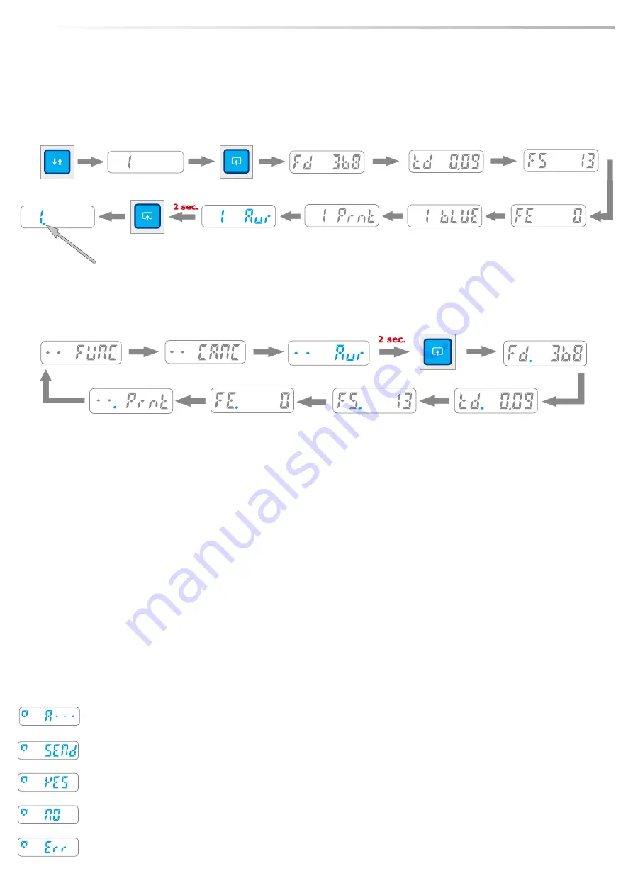
ARITHMETICAL AVERAGE OF THE TEST VALUES 

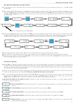
 To calculate the average, proceed as follows: any three of the tests performed can be used to calculate the average, e.g. : Test 

01

, Test 

02


n

and Test  

04

.

 After reading the Test 

01

 parameters, the 

right

 button can be used to make the CANC   function appear, followed by the 

Aur

 function. 

n

Pressing the 

right 

down for 

2

 seconds makes the Aur function disappear and the test is 

marked

 with a dot underneath it; this shows that 

Test 

01

 has 

been selected

 for calculation of the average. Now the two other tests must be selected (Tests 02 and 04) in the same way as 

described above.


Once the test 

selection 

operation is complete, the 

FUNC 

menu (always available between the first and last test) must be opened; next find 

n

the 

Aur 

function (straight after CANC), and press the 

right

 button for 

2

 seconds to activate the average calculation function immediately; 

the parameters are displayed in a cycle in which the user can move from one value to the next by quick-pressing the 

right

 button.

 The average parameter reading function 

Aur 

can only be accessed if at least one test has already been selected.

n

 NOTE: After the average parameters have been read, an additional function (

.Prnt

) allows them to be printed (see detail on page 

6

)

n

 When the gauge is switched off, the tests 

“selected” 

for the average calculation are automatically 

“unselected” 

(the parameters and the 

n

tests stored in the instrument are not erased).

Instrument Functions - Detail


PC ON MODE - DETAILS

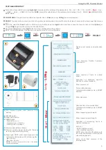
 The 

PC ON

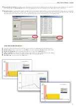
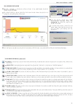
 mode has been designed to use the instrument in conjunction with the BlueForce program on PC and enables the direct display of 

n

the test graph on the PC screen for an evaluation of the results in real time, depending on the type of port selected on the software. In this 
case the instrument must first be connected to the PC via the USB cable or special Bluetooth adaptor (follow the instructions for installation 
of the software and drivers on pages

 9

 and 

10

).

 This function, signalled by a small box at the top left of the instrument display, disables memorisation of the tests in the internal memory, as 

n

all data are transferred directly to the PC. 

In PC-ON mode, the SMART interfaces are not enabled

 The previous paragraph describes the method for setting 

PC ON

, while to restore the instrument to normal mode (with test storage and 

n

display) press the 

right 

button for 

2

 seconds, after which the message 

PC OFF

 flashes on display awaiting confirmation, then press the 

right 

button again for 

seconds; at this point, the instrument will be reset to the default operating mode.

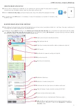
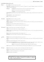
 BEHAVIOR IN DISPLAY-OFF MODE (PC ON):

 In display-off mode, it is always present the red square on the left, together with the 

n

advices : Acquiring, Sending, etc.


TESTS ACQUISITION:

 During tests acquisition (6 seconds), the display shows

 (A---)

, (Acquiring) together with three 

n

dashes.


DATA SENDING:

 During data sending to pocket-PC, the display shows 

(SENd)

.

n


POSITIVE RESPONSE:

  In the case of positive response to the test carried out, the display shows 

(YES)

.

n


NEGATIVE RESPONSE:

 In the case of negative response to the test carried out, the display shows 

(NO)

.

n


ERROR CHECK:

 if it occurs any internal errors, the display shows 

Err1

 or 

Err2

 etc. until any key is pressed (See 

MORE 

n

DISPLAY MESSAGGES

 page 

4

).

test is marked with a dot underneath 

Summary of Contents for BlueForce Smart

Page 1: ......

Page 2: ...sts performed within a client database with the option of printing out reports with relative graphs The SMART features of the Came Test allows the integrated NFC or Bluetooth hardware to see the data of the tests taken with the relative graphics directly on smartphone and tablets INDEX n Came Test specifications Page 1 n Initial Use Instrument Functions Page 2 3 n Instrument Functions Detail Page ...

Page 3: ...ent tip detects a force exceeding the minimum threshold the test acquisition n process is started 6 sec The display shows the test number and the letter A followed by 3 dashes SEND TEST for SMART enabled devices only After acquisition dots will appear at the bottom of the display scrolling n towards the right to indicate that the test is being sent to the iOS or NFC device If there are no enabled ...

Page 4: ...button to view the TIME CANC DELETING A SINGLE TEST To delete the current test in the example no 4 press the right button for approx 2 seconds when the text 4 DEL flashes on display to indicate awaiting confirmation press the right button again for 2 sec to permanently delete the selected memory slot READ OF TESTS PRACTICAL EXAMPLE Let s imagine the follow situation n test 01 saved n test 02 saved...

Page 5: ...2 seconds and briefly press the right button to change the day month year as required To change the number briefly press the left button or press and hold the latter to change the direction of modification increase decrease after this press and hold the right button to save the changes and exit NOTE Date and time setting is only available for models with internal clock not Upgrade n CAL date of la...

Page 6: ...onjunction with the BlueForce program on PC and enables the direct display of n the test graph on the PC screen for an evaluation of the results in real time depending on the type of port selected on the software In this case the instrument must first be connected to the PC via the USB cable or special Bluetooth adaptor follow the instructions for installation of the software and drivers on pages ...

Page 7: ...nal Li ion battery a ON OFF button b Paper FEED button C POWER light Steady blue on Flashing blue stand by Flashing red no paper 2 Power supply battery charger 3 Thermal printing paper load with the edge face up as shown in the picture 4 Paper type NOTE order original paper or rolls of thermal printing paper in the following size W 58 mm D max 40 mm NOTE If printed characters are faint the battery...

Page 8: ...n menu or the settings menu 3 Start the BlueForce Smart App on the device 4 Perform a test with the instrument after 6 seconds acquisition the test is sent scrolling dots will appear on the display to indicate that the test is being sent to the device 5 If your device is compatible and enabled for the smart functions the test with its graph will be displayed to go ahead and use the BlueForce Smart...

Page 9: ...he required test with the Came Test instrument the device smartphone tablet etc will show this page containing all n information on the measurements taken see details below To display to correct graph according to the effective port and measurement point the correct selection must be made via the relative n icon setting of the measurement type and points then confirming by pressing OK Confirm to r...

Page 10: ...two files onto the computer desktop n Run the Setup file and enable installation n WARNING The file is not harmful and enables allows your Browser or Antivirus program to download the file Setup_blu_came_en zip or update_blueforce_en zip Proceed with guided installation of the BlueForce n click Continue Click Close to end installation of BlueForce n n IMPORTANT Before starting installation of the ...

Page 11: ...me one Wait a few seconds for the n Drivers of the new Hardware to be installed see pop up in the applications bar STARTING THE SOFTWARE Run the BlueForce software from the desktop icon n When it is started the first time the user has to select the type of device used USB cable or Bluetooth device n Select the PC connection mode n Connect the instrument with the USB lead or connect the Bluetooth d...

Page 12: ...nagement n Then select Device Menager It will show the Device Menager tree n Connect instrument or Plug Go device n The USB Serial Port will be shown with the relative serial number in the COM and LPT Ports n hardware group Start the BlueForce software and open the menu File Settings Serial Port n Select the exact COM port a black dot appears on the left n If the DRIVERS cannot be found repeat ins...

Page 13: ...the SEND n function on the instrument to send the tests to the software Tests sended to the program are placed on the top at the left if there are more than one test the list increases to the bottom n Each test can be identified by the progressive number and the date 2 A dot will appear beside each test green indicates a positive result n red a negative result The assessment based on the port type...

Page 14: ...ied out at the points listed by the software and then finally select the door You can now view a print preview to check that all the data entered is correct then proceed with the printout Remark The report can be printed in the PDF format in which it is drawn up n N B The result of the measurements is reprocessed automatically by the software when the tests are copied or moved from the test lists ...

Page 15: ...s and the measuring points associated with them with the relative impact test files Exported client files are organized as follows one directory client name contains one file named clientname txt and as many directories door name as there are closure types associated with the client For a description of the contents of the directories door name see the section on the Export door to file command n ...

Page 16: ...hat have been wrongly associated with other measuring points or exported using the Export client and Export door to file commands UTILITIES AND GRAPH DISPLAY The graph utilities function allows the user to perform a more in depth analysis of the impact curve n Export to file exports impact test file to txt file in a format importable by Excel force time table n Export to bitmap file exports impact...

Page 17: ... possible to insert or n modify customer data ERASE CUSTOMER If customer has no gates associated it shows a confirmation form if you click on OK the customer selected will n be cancelled It is not allowed to cancel a customer that has one or more gates associated proceed first with the cancellation of gates NEW GATE This option is active only when a customer is selected It permits the creation of ...

Page 18: ...ected customer It is possible to eliminate a customer only it he has no gates associated first eliminate gates Detail It shows data of selected customer name address v a t New gate It permits the creation of a new gate associated to the selected customer Gate Modify It permits to modify gate data reference type location n Delete It eliminates the gate selected It is possible to eliminate a gate on...

Page 19: ...ionals n CARES FOR PROPER USE OF THE INSTRUMENT ATTENTION Follow the rules of proper use and safety on work ATTENTION Don t expose the instrument to high temperature 80 C ATTENTION Don t dip the instrument in any liquid 4 1 2 3 ON SITE MEASUREMENT POSITIONS 1 Position on sliding leaf instrument with straight accessory total 30 cm n 2 Position on sliding leaf instrument with straight accessory plus...

Page 20: ...trument holder n Push with strenght and then turn the spacer following the joint n If necessary add the additional spacer for 50cm measures n JOINT ACCESSORIES Picture 5 To assemble accessories and spacers correctly it is necessary to insert with strenght the tube n with spindle aligned to reference notch and then turn of 180 to insert the joint secur lock ANGULAR ACCESSORY Picture 6 7 To assemble...

Page 21: ...is necessary to use proper extensions For example in barriers the extension must be fixed to ground and must have the possibility to adjust height and tilt How the resultant graph is to be interpreted n The resultant test graph rapresents the diagram of Force amplitude expressed in Newton on vertical ax versus Time duration expressed C in seconds on horizontal ax The interpretation of diagram in t...

Page 22: ...ILITY REMARK The indication of NEGATIVE RESPONSE POSITIVE RESPONSE returned by instrument and or by software must be considered n merely a suggestion Microtronics Srl is not responsible in any way for any possible damage or injury to people things that may come from wrong interpretation n of tests results or from improper use of the instrument SOFTWARE USER LICENCE It is granted only one user lice...

Page 23: ...rror margin range from 25 to 200N 0 5 F S from 200N to 1000N 1 F S from 1000 to n 2000N 2 F S CE EMC conformity at TUV Rheinland on sample BlueForce instrument serial no 00981 n Compliant with standards EN12445 EN12453 EN16005 EN60335 2 95 DHF TS 011 2016 n NFC interface standard ISO IEC 14443 and NFC Forum Type 4 n BLE interface Bluetooth version 4 1 n USB interface v 2 0 specification compliant ...

Page 24: ......

Reviews: