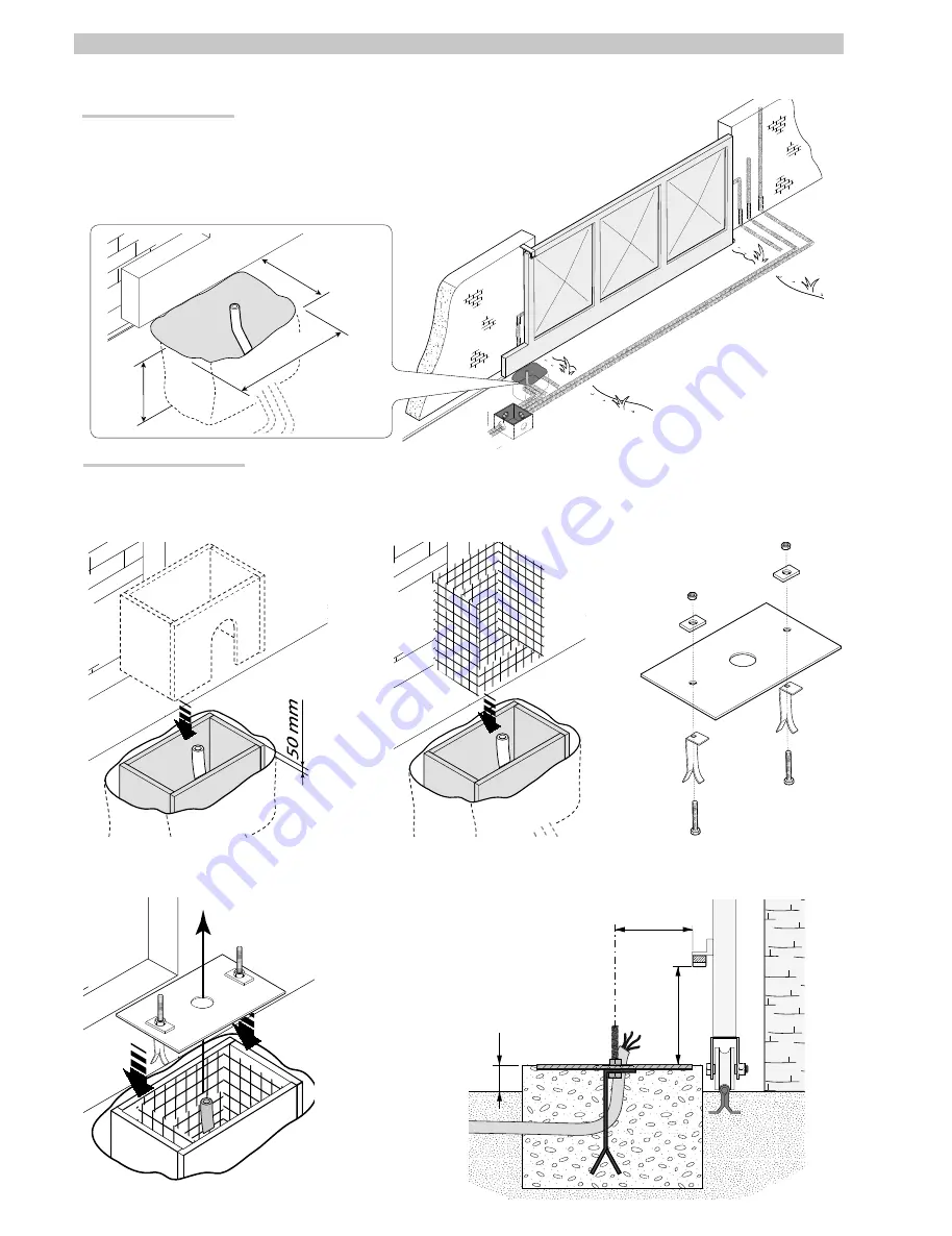
400
600
400
50
142
220
Pa
g
e
6
- M
an
u
al
c
od
e:
11
9
B
W
4
1
E
N
11
9
B
W
4
1
E
N
ve
rs
.
4
04/
2
0
14 © C
A
M
E c
an
ce
lli
auto
m
ati
ci
s.p.a. - T
h
e d
ata a
n
d i
nf
or
m
ati
on p
rovi
d
ed
in
th
is
m
an
u
al
a
re s
u
b
je
ct to c
h
an
g
e at a
ny ti
m
e w
ith
ou
t p
ri
or n
oti
ce
by C
A
M
E C
an
ce
lli
A
uto
m
ati
ci
S
.p.a.
INSTALLATION
⚠
The following illustrations are only examples, given that the space for securing the operator and accessories varies depending on the overall dimensions. The
installation technician is responsible for choosing the most suitable solution.
Installing corrugated tubes
Drill the hole for the counterframe.
Prepare the junction boxes and corrugated tubes necessary for the connections from the inspection chamber. In order to
connect the gearmotor, a Ø 60 mm corrugated tube is advisable. Ø 25 mm pipes are recommended for accessories, on
the other hand.
N.B. the number of tubes depends on the type of system installed and any accessories.
Installing the mounting plate
Prepare a counterframe that is larger than the mounting plate and place it in the hole. The counterframe must protrude 50 mm from ground level.
Insert an iron grid inside the counterframe to reinforce the concrete.
Secure the anchor brackets to the plate using the screws, nuts and washers supplied.
Position the mounting plate, respecting the measurements shown on the drawing, if the rack is already present.
Caution! The tube must pass through the prepared hole.
All manuals and user guides at all-guides.com
all-guides.com


