Craftsman 139.53403, Owner'S Manual
Looking for the Owner's Manual for Craftsman 139.53403? Look no further! Download the manual for free from manualshive.com, your go-to source for user manuals. Find all the important instructions and guidance you need to operate and maintain your Craftsman product efficiently. Simplify your experience with the Craftsman 139.53403 manual, just a click away.
Share
Download


Reviews:
No comments
Related manuals for 139.53403

GEKO-L
Brand: O&O Pages: 24

Estate Swing
Brand: FAAC Pages: 25

748
Brand: FAAC Pages: 15

DAAB EP104
Brand: FAAC Pages: 12

Safe Zone S418
Brand: FAAC Pages: 30

ECOPESI
Brand: Ribind Pages: 12

ZC3C
Brand: CAME Pages: 12

21.042.10
Brand: EINHELL Pages: 48

Speedroller
Brand: Novoferm Pages: 46

Security+ 3275
Brand: Chamberlain Pages: 36

SGS 501
Brand: SOMFY Pages: 72

FREEVIA 400
Brand: SOMFY Pages: 72

610
Brand: Haas Door Pages: 14

CanPRO 56050-()
Brand: Nemco Pages: 5

Security+ 2585
Brand: Chamberlain Pages: 36
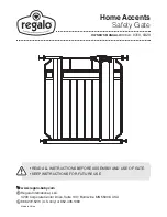
Home Accents 0310
Brand: Regalo Pages: 16

C450C
Brand: Chamberlain Pages: 88

C273
Brand: Chamberlain Pages: 88


