List of Tables
Page xviii
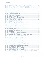
Table 40 RJ45 connector and spare gland part numbers ................................................. 2-33
Table 41 LPU and grounding kit contents ....................................................................... 2-34
Table 42 LPU and grounding kit part number ................................................................. 2-35
Table 43 Cable grounding kit part numbers .................................................................... 2-35
Table 44 List of AP external antennas ............................................................................. 2-36
Table 45 PTP 450i Series BH or PMP 450/450i Series SM external antenna ................... 2-36
Table 46 RF cable and connector part numbers .............................................................. 2-37
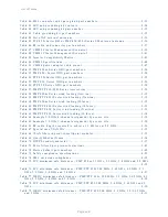
Table 47 CMM5 Cluster Management Scenario 1 ........................................................... 2-39
Table 48 CMM5 Cluster Management Scenario 2 ........................................................... 2-41
Table 49 Injector Compatibility Matrix ............................................................................ 2-43
Table 50 CMM5 Specifications ........................................................................................ 2-44
Table 51 CMM4 power adapter cable pinout ................................................................... 2-47
Table 52 PMP 450m Series ODU part numbers ............................................................... 2-54
Table 53 PMP 450i Series ODU part numbers ................................................................. 2-54
Table 54 PTP 450i Series ODU part numbers .................................................................. 2-55
Table 55 PMP 450 Series ODU part numbers .................................................................. 2-56
Table 56 PTP 450 Series ODU part numbers ................................................................... 2-58
Table 57 PMP/PTP 450/450I Series Accessories .............................................................. 2-59
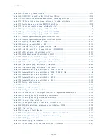
Table 58 PMP 450m Series wind loading (Newton) ......................................................... 3-12
Table 59 PMP/PTP 450i Series wind loading (Newton) .................................................... 3-12
Table 60 PMP 450m Series wind loading (lb force) ......................................................... 3-12
Table 61 PMP/PTP 450i Series wind loading (lb force) .................................................... 3-13
Table 62 PMP/PTP 450 Series wind loading (Newton) ..................................................... 3-13
Table 63 PMP/PTP 450 Series wind loading (lb force) ..................................................... 3-14
Table 64 Example 5.8 GHz 4-channel assignment by access site ..................................... 3-19
Table 65 Example 5.8 GHz 3-channel assignment by access site ..................................... 3-20
Table 66 RF cable lengths required to achieve 1.2 dB loss at 5.8 GHz ............................ 3-26
Table 67 Special case VLAN IDs ...................................................................................... 3-32
Table 68 VLAN filters in point-to-multipoint modules ...................................................... 3-33
Table 69 Q-in-Q Ethernet frame ....................................................................................... 3-34
Table 70 HTTPS security material ................................................................................... 3-37
Table 71 Ports filtered per protocol selections ................................................................ 3-42
Table 72 Device default port numbers ............................................................................. 3-42
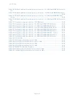
Table 73 Safety compliance specifications ....................................................................... 4-22
Table 74 EMC emissions compliance ............................................................................... 4-22
Table 75 FCC minimum safe distances – PMP 450m 5.1 GHz, 5.2 GHz, 5.4 GHz and 5.8 GHz
................................................................................................................................... 4-25
Table 76 FCC minimum safe distances – PMP/PTP 450i 900 MHz, 3.65 GHz, 4.9 GHz, 5.1
GHz, 5.2 GHz, 5.4 GHz and 5.8 GHz .......................................................................... 4-27
Table 77 ISEDC minimum safe distances – PMP/PTP 450i, 900 MHz, 3.5 GHz, 3.65 GHz, 4.9
GHz, 5.2 GHz, 5.4 GHz, and 5.8 GHz ......................................................................... 4-28
Table 78 FCC minimum safe distances – PMP/PTP 450 900 MHz, 2.4 GHz, 3.65 GHz and 5
GHz ............................................................................................................................ 4-30
Table 79 ISEDC minimum safe distances – PMP/PTP 450 900 MHz, 2.4 GHz, 3.5/3.65 GHz
and 5 GHz .................................................................................................................. 4-31
Summary of Contents for PMP 450 Series
Page 125: ...Chapter 3 System planning Typical deployment Page 3 3 Figure 37 Wall installation...
Page 126: ...Chapter 3 System planning Typical deployment Page 3 4 Figure 38 Roof installation...
Page 127: ...Chapter 3 System planning Typical deployment Page 3 5 Figure 39 GPS receiver wall installation...


