Chapter 3: System planning
Site planning
Page 3-8
Power supply site selection
When selecting a site for the ODU power supply, consider the following factors:
Indoor location with no possibility of condensation, flooding or high humidity.
Availability of a mains electricity supply.
Located in an environment where it is not likely to exceed its operational temperature rating,
allowing for natural convection cooling.
Accessibility for viewing status indicator LED and connecting Ethernet cables.
Cable lengths; see
Error! Reference source not found.
on page
2-25
.
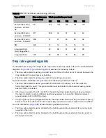
Maximum cable lengths
When installing PMP/PTP 450i Series ODU, the maximum permitted length of the shielded copper
Ethernet interface cable is 330 feet (100m) from AP/BHM/SM/BHS to their associated power
supplies or CMM4.
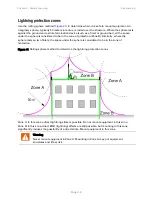
Grounding and lightning protection
Warning
Electro-magnetic discharge (lightning) damage is not covered under warranty. The
recommendations in this guide, when followed correctly, give the user the best
protection from the harmful effects of EMD. However 100% protection is neither
implied nor possible.
Structures, equipment and people must be protected against power surges (typically caused by
lightning) by conducting the surge current to ground via a separate preferential solid path. The
actual degree of protection required depends on local conditions and applicable local regulations.
To adequately protect a PMP/PTP 450 Platform installation, both ground bonding and transient
voltage surge suppression are required.
Full details of lightning protection methods and requirements can be found in the international
standards IEC 61024-1 and IEC 61312-1, the U.S. National Electric Code ANSI/NFPA No. 70-1984 or
section 54 of the Canadian Electric Code.
Warning
International and national standards take precedence over the requirements in this
guide.
Summary of Contents for PMP 450 Series
Page 125: ...Chapter 3 System planning Typical deployment Page 3 3 Figure 37 Wall installation...
Page 126: ...Chapter 3 System planning Typical deployment Page 3 4 Figure 38 Roof installation...
Page 127: ...Chapter 3 System planning Typical deployment Page 3 5 Figure 39 GPS receiver wall installation...

