background image

Chapter 4:  Legal and regulatory information 

Compliance with radio regulations 


Page 4-34 

Type approvals 

This system has achieved Type Approval in various countries around the world. This means that 
the system has been tested against various local technical regulations and found to comply. The 
frequency bands in which the system operates may be ‘unlicensed’ and, in these bands, the 
system can be used provided it does not cause interference. The system is not guaranteed 
protection against interference from other products and installations. 
The radio specification type approvals that have been granted for 450 Platform Family frequency 
variants are listed under 

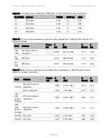
Table 84

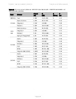
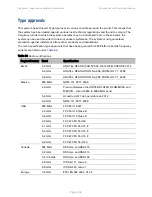
Table 84 Radio certifications 

Region/Country  Band 

Specification 

Brazil 

4.9 GHz 

ANATEL, RESOLUÇÃO Nº 633, DE 14 DE MARÇO DE 2014 

5.4 GHz 

ANATEL, RESOLUTION No. 506, FROM JULY 1, 2008 

5.8 GHz 

ANATEL, RESOLUTION No. 506, FROM JULY 1, 2008 

Mexico 900 

MHz NOM-121-SCT1-2009 

4.9 GHz 

Protocol Between the UNITED STATES OF AMERICA and 
MEXICO – Use of 4940 to 4990 MHz band. 

5.4 GHz 

Acuerdo del 27 de noviembre de 2012 

5.8 GHz 

NOM-121-SCT1-2009 

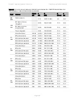
USA 

900 MHz 

FCC Part 15.247 

2.4 GHz 

FCC Part 15 Class B 

3.6 GHz 

FCC Part 15 Class B 

4.9 GHz 

FCC 47 CFR Part 90 

5.1 GHz 

FCC 47 CFR Part 15 E 

5.2 GHz 

FCC 47 CFR Part 15 E 

5.4 GHz 

FCC 47 CFR Part 15 E 

5.8 GHz 

FCC 47 CFR Part 15 C 

Canada  

900 MHz 

RSS Gen and RSS 210 

2.4 GHz 

RSS Gen and RSS 210 

3.5 /3.6 GHz 

RSS Gen and RSS 192 

4.9 GHz 

IC RSS-111, Issue 5 

5.8 GHz 

IC RSS-247, Issue 1 

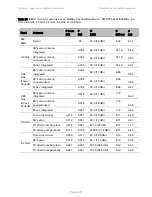
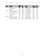
Europe 

3.5 GHz 

ETSI EN 302 326-2 V1.2.2 

Summary of Contents for PMP 450 Series

Page 1: ...33F Cambium 450 Platform User Guide System Release 15 0 3 For Regulatory Review Only inclusion of 40 MHz Channel Size pass...

Page 2: ...aterial Accordingly any copyrighted material of Cambium its licensors or the 3rd Party software supplied material contained in the Cambium products described in this document may not be copied reprodu...

Page 3: ...gnements specifiques au Canada 6 EU Declaration of Conformity 7 Specific expertise and training for professional installers 7 Ethernet networking skills 7 Lightning protection 8 Training 8 Problems an...

Page 4: ...are 2 1 System Components 2 2 Point to Multipoint PMP 2 2 Backhaul PTP 2 5 450 Platform Family interfaces 2 7 Diagnostic LEDs 2 13 Power supply options 2 16 ODU mounting brackets accessories 2 23 Ligh...

Page 5: ...er 3 System planning 3 1 Typical deployment 3 2 ODU with PoE interface to PSU 3 2 Site planning 3 7 Site selection for PMP PTP radios 3 7 Power supply site selection 3 8 Maximum cable lengths 3 8 Grou...

Page 6: ...dresses 3 30 Translation bridging 3 31 Engineering VLANs 3 31 Network management planning 3 35 Planning for SNMP operation 3 35 Enabling SNMP 3 35 Security planning 3 36 Isolating AP BHM from the Inte...

Page 7: ...radio frequency energy 4 22 Compliance with radio regulations 4 33 Type approvals 4 34 Brazil specific information 4 35 Australia Notification 4 35 Regulatory Requirements for CEPT Member States www...

Page 8: ...Install the main drop cable 6 18 Install the bottom LPU to PSU drop cable 6 20 Installing external antennas to a connectorized ODU 6 22 PMP 450i Series 6 22 PMP 450 Series 6 30 Attaching the PMP 450...

Page 9: ...sion Status of the AP BHM to determine test registration 7 20 Configuring IP and Ethernet interfaces 7 23 Configuring the IP interface 7 24 Auxiliary port 7 27 NAT DHCP Server DHCP Client and DMZ 7 28...

Page 10: ...Setting up SNMP agent 7 170 Configuring SM BHS s IP over the air access 7 171 Configuring SNMP 7 172 Configuring syslog 7 177 Syslog event logging 7 178 Configuring system logging 7 178 Configuring r...

Page 11: ...Data Accounting 7 238 RADIUS Device Re authentication 7 241 RADIUS Change of Authorization and Disconnect Message 7 242 Microsoft RADIUS support 7 243 Cisco ACS RADIUS Server Support 7 247 Configurin...

Page 12: ...nterpreting Overload statistics 9 50 Interpreting DHCP Relay statistics 9 52 Interpreting Filter statistics 9 54 Viewing ARP statistics 9 55 Viewing NAT statistics 9 55 Viewing NAT DHCP Statistics 9 5...

Page 13: ...ation 10 63 Chapter 11 Troubleshooting 11 1 General troubleshooting procedure 11 2 General planning for troubleshooting 11 2 General fault isolation process 11 3 Secondary Steps 11 4 Troubleshooting p...

Page 14: ...2 24 Figure 16 PMP PTP 450i Series ODU rear interfaces 2 25 Figure 17 PMP PTP 450i Series Connectorized ODU antenna interfaces 2 26 Figure 18 Outdoor drop cable 2 28 Figure 19 Optical SFP transceiver...

Page 15: ...n building 6 17 Figure 61 RJ45 cable 6 19 Figure 62 AP antenna parts 6 24 Figure 63 Antenna top plate 6 25 Figure 64 Attaching antenna plate to the AP 6 25 Figure 65 Attaching the plate 6 26 Figure 66...

Page 16: ...7 12 Figure 105 Regional Settings tab of AP BHM 7 13 Figure 106 Radio Carrier Frequency tab of AP BHM 7 14 Figure 107 Synchronization tab of AP BHM 7 15 Figure 108 LAN IP Address tab of the AP BHM 7...

Page 17: ...ion 7 240 Figure 148 Device re authentication configuration 7 241 Figure 149 RADIUS CoA configuration for AP 7 242 Figure 150 EAPPEAP settings 7 243 Figure 151 Importing certificate in NPS 7 244 Figur...

Page 18: ...e SM 8 50 Figure 177 Sessions tab of the AP 8 51 Figure 178 Remote Subscribers page of AP 9 27 Figure 179 Event log data 9 28 Figure 180 Network Interface tab of the AP 9 30 Figure 181 Network Interfa...

Page 19: ...5 GHz 2 10 Table 18 AP BHM LED descriptions 2 14 Table 19 SM BHS LED descriptions 2 15 Table 20 PSU part numbers for PMP 450m AP 2 16 Table 21 PSU part numbers for PMP PTP 450i Series 2 17 Table 22 AC...

Page 20: ...ing lb force 3 12 Table 61 PMP PTP 450i Series wind loading lb force 3 13 Table 62 PMP PTP 450 Series wind loading Newton 3 13 Table 63 PMP PTP 450 Series wind loading lb force 3 14 Table 64 Example 5...

Page 21: ...Example 7 46 Table 101 AP BHM VLAN tab attributes 7 48 Table 102 Q in Q Ethernet frame 7 49 Table 103 SM VLAN attributes 7 51 Table 104 SM VLAN Membership attributes 7 55 Table 105 BHM VLAN page attri...

Page 22: ...x of multicast and unicast traffic scenarios 7 160 Table 145 450 Platform Family AP SM BH Custom Frequencies page 5 GHz 7 162 Table 146 PMP PTP 450 SM BH Custom Frequencies page 3 65 GHz 7 163 Table 1...

Page 23: ...187 Color code versus uplink downlink rate column 8 45 Table 188 Link Status page attributes AP BHM 8 46 Table 189 Link Status page attributes SM BHS 8 48 Table 190 General Status page attributes PMP...

Page 24: ...ifications 10 31 Table 233 PMP PTP 450 power supply specifications part number N000900L001A 10 32 Table 234 450m 450i Series Main and Aux Ethernet bridging specifications 10 33 Table 235 450 Series Et...

Page 25: ...ry 3 65 GHz band PMP PTP 450 Series 10 50 Table 257 Frequency range per country 4 9 GHz band PMP PTP 450i Series 10 51 Table 258 Frequency range per country 5 4 GHz band PMP PTP 450i Series 10 52 Tabl...

Page 26: ...ry information Chapter 5 Preparing for installation Chapter 6 Installation For system configuration tools and troubleshooting refer to the following chapters Chapter 7 Configuration Chapter 8 Tools Ch...

Page 27: ...tion conventions in document This document covers Cambium 450 Series 450i Series and 450m Series products The following notation conventions are followed while referring to product series and product...

Page 28: ...the references This document is divided into numbered chapters that are divided into sections Sections are not numbered but are individually named at the top of each page and are listed in the table o...

Page 29: ...features to prevent interference to weather radar systems that operate in the band 5600 MHz to 5650 MHz These features must be implemented in all products able to operate outdoors in the band 5470 MH...

Page 30: ...e master is outside the 35 km 22 miles radius but communicates with outdoor clients which may be within the 35 km 22 miles radius of the TDWRs If interference is not eliminated a distance limitation b...

Page 31: ...aux deux conditions suivantes 1 l appareil ne doit pas produire de brouillage et 2 l utilisateur de l appareil doit accepter tout brouillage radio lectrique subi m me si le brouillage est susceptible...

Page 32: ...SEDC La liste des antennas approve s pour l operation au Canada est founie dans le chapitre Country specific radio regulations Innovation Science and Economic Development Canada ISEDC tableaux Table 2...

Page 33: ...and Chapter 3 System planning Training The installer needs to have basic competence in radio and IP network installation The specific requirements applicable to the 450 Platform should be gained by r...

Page 34: ...te of shipment from Cambium Networks or a Cambium distributor Cambium Networks warrants that hardware will conform to the relevant published specifications and will be free from material defects in ma...

Page 35: ...ecurity practices Security aspects to be considered are protecting the confidentiality integrity and availability of information and assets Assets include the ability to communicate information about...

Page 36: ...llowing format Warning Warning text and consequence for not following the instructions in the warning Cautions Cautions precede instructions and are used when there is a possibility of damage to syste...

Page 37: ...n EU countries Disposal of Cambium equipment European Union EU Directive 2002 96 EC Waste Electrical and Electronic Equipment WEEE Do not dispose of Cambium equipment in landfill sites For disposal in...

Page 38: ...d in this chapter Overview of the 450 Platform Family on page 1 2 introduces the key features typical uses product variants and components of the 450 Platform Family Wireless operation on page 1 14 de...

Page 39: ...t need to forward 450 Platform Family The 450 Series platform supports following PMP 450m Series PMP PTP 450i Series PMP PTP 450 Series PMP 450m Series The PMP 450m Series AP is a revolutionary produc...

Page 40: ...1000Base T Ethernet Main port with PoE input Operating frequencies 5 150 to 5 925 GHz Tx Power max 24 dBm Channel bandwidth 20 MHz High spectral efficiency More than 40 bps Hz Timing synchronization...

Page 41: ...nd performance that is consistent regardless of SM BHS loading A range of cost effective subscriber device solutions to meet the business case of any network application MIMO B Mode This technique pro...

Page 42: ...s ODU can operate in the following bands 900 MHz band 902 to 928 MHz 5 GHz band 4900 to 5925 MHz o 4 9 GHz band 4940 to 4990 MHz o 5 1 GHz band 5150 to 5250 MHz o 5 2 GHz band 5250 to 5350 MHz o 5 4 G...

Page 43: ...z Integrated 16 dBi 90 sector antenna Connectorized Use with an external antenna PMP 450i SM 3 3 to 3 9 GHz Integrated 19 dBi SM BH with MARS antenna 4 9 to 5925 GHz support 4 9 5 1 5 2 5 4 and 5 8 GH...

Page 44: ...loading A range of cost effective subscriber device solutions to meet the business case of a network application MIMO B Mode This technique provides for the ability to double the throughput of a radio...

Page 45: ...TP 450 Series ODU can operate in the following bands 900 MHz band 902 to 928 MHz SM only 2 4 GHz band 2400 to 2483 MHz 3 5 GHz band 3300 to 3600 MHz 3 65 GHz band 3500 to 3850 MHz 5 4 GHz band 5470 to...

Page 46: ...d Use with an external antenna Integrated 17 dBi H V PMP 450 SM 900 MHz Connectorized Use with an external antenna 2 4 GHz Connectorized Use with an external antenna Integrated 7 dBi Dual Slant integr...

Page 47: ...0i SM Greenfield 4 9 5 1 5 2 and 5 9 GHz PMP 450i AP PMP 450i SM Greenfield 5 4 and 5 8 GHz PMP 450m AP PMP 450i SM PMP 450 SM and PMP 450d SM PMP 450 AP 3 GHz PMP 450i AP 3 GHz PMP 450i SM 3 5 GHz PM...

Page 48: ...reless bridge across sites Each site installation consists of an Integrated or Connectorized outdoor unit ODU and a power supply PSU see Figure 1 The ODU provides the following interfaces Ethernet por...

Page 49: ...applications nLOS video surveillance in metro areas Urban area network extension Network extension into areas with foliage Point to Point Backhaul The PTP configuration of 450 Platform Family consists...

Page 50: ...gain design for 5 GHz band An indoor power supply module providing Power over Ethernet PoE supply to ODU AP SM BH Antennas and antenna cabling Connectorized ODUs require external antennas connected us...

Page 51: ...ts SM BHS Furthermore collocated APs BHMs must be synced together an unsynchronized AP BHM that transmits during the receive cycle of a collocated AP BHM can prevent a second AP BHM from being able to...

Page 52: ...at the expense of using more bandwidth Systems configured for a narrower channel bandwidth provide better receiver sensitivity and can also be an appropriate choice in deployments where the amount of...

Page 53: ...SM BHS or due to obstructions or if interference affects the RF environment the system automatically and dynamically adjusts the links to the best operation level The system chooses its modulation rat...

Page 54: ...FDM techniques and a high link budget there is a high probability of a robust connection over a non line of sight path The sub features that comprises the MIMO techniques utilized in the 450 Platform...

Page 55: ...reless conditions between itself and the node and know to expect these same conditions to be applied to other communications from that node This is known as channel sounding Channel estimation and sou...

Page 56: ...transfer protocol secure HTTPS RADIUS authentication Simple network management protocol SNMP v2c and v3 Network time protocol NTP System logging Syslog Wireless Manager WM software Canopy Network Upd...

Page 57: ...accounts each of which may have one of the four possible roles ADMINISTRATOR who has full read and write permissions This is the level of the root and admin users as well as any other administrator ac...

Page 58: ...ogoff for each username on the RADIUS server This accounting does not track and report specific configuration actions performed on radios or pull statistics such as bit counts from the radios Such fun...

Page 59: ...owerful user interface you can not only be able to control your network s access distribution and backhaul layers but can also have visibility to WLAN sites and be able to quickly launch indoor networ...

Page 60: ...elements that you select o Only network branches that you select Provides a Script Engine that you can use with any script which o The user can define o Cambium supplies CNUT is available at http www...

Page 61: ...ecovery Console mode supports Restoring factory default IP address 169 254 1 1 and password Boot with factory default Canopy system software settings Load previously installed SW images See Radio Reco...

Page 62: ...ts of PTP and PMP including its accessories Error Reference source not found on page Error Bookmark not defined describes various cable and lightning protection Antennas and antenna cabling on page 2...

Page 63: ...eries and PMP 450 Series ODUs are supplied in Integrated or Connectorized configurations The PMP 450m Series AP is supplied in Integrated configuration only See Table 2 PMP 450m Series hardware config...

Page 64: ...zed 4900 5925 MHz 5 10 15 20 30 40 MHz 27 dBm Integrated 16 dBi 90 degree RoW Connectorized Integrated 23 dBi Canada Connectorized Integrated 23 dBi RoW DES Connectorized Integrated 23 dBi 5 GHz PMP 4...

Page 65: ...M Connectorized 3300 3600 MHz 5 7 10 15 20 30 40 MHz 25 dBm Integrated 8 dBi Integrated 19 dBi 3 65 GHz PMP 450 AP FCC ISM Connectorized 3500 3850 MHz 5 7 10 15 20 30 40 MHz 25 dBm Integrated 16 dBi 3...

Page 66: ...rized ODU See Table 4 PMP PTP 450i Series hardware configurations on page 1 6 See Table 6 PMP PTP 450 Series hardware configurations on page 1 9 Product variants Table 13 PTP 450i Series variants Vari...

Page 67: ...65 GHz PTP 450 BH ROW Connectorized 3500 3850 MHz 5 7 10 15 20 30 MHz 25 dBm Integrated 16 dBi Integrated 19 dBi 5 4 5 8 GHZ PTP 450 BH FCC Connectorized 5470 5875 MHz 5 10 20 MHz 22 dBm Integrated 1...

Page 68: ...descriptions and cabling Interface Function Cabling PSU Ethernet Power over Ethernet Ethernet communications management and data CMM5 sync over power synchronization input RJ45 Cable See Table 86 on p...

Page 69: ...k with CMM4 like PMP 450 450i Series Note SFP kits part numbers C000065L008A and C000065L009A are required for SFP port connectivity SFP port is not supported in system release 15 0 15 0 0 1 PMP PTP 4...

Page 70: ...output UGPS power output RJ 45 Cable See Table 87 on page 5 11 Audio tones Data RF Port A Vertical RF connection to antenna 50 ohm RF cable N type RF Port B Horizontal RF connection to antenna 50 ohm...

Page 71: ...UGPS module Default plug port RJ11 cable default plug RF Port A 2 4 GHz 45 degree RF connection to AP antenna 50 ohm RF cable N type 5 GHz Vertical RF connection to AP antenna RF Port B 2 4 GHz 45 deg...

Page 72: ...2 11 Figure 5 PMP PTP 450 Series SM BH Connectorized interfaces Note As per UL guidelines the Ground Lug on the radiated SM is not required External antenna cable path A labeled A Ground connectorize...

Page 73: ...Chapter 2 System hardware System Components Page 2 12 Figure 6 PMP 450d Series SM Integrated Dish Figure 7 PMP 450 Series SM 3 GHz Integrated Figure 8 PTP 450 Series BHM BHS...

Page 74: ...LED The LED color does not indicate any status AP BHM LEDs The diagnostic LEDs report the information about the status of the AP BHM Figure 9 AP BHM diagnostic LEDs viewed from unit front ODU LED Dis...

Page 75: ...ransfer Frequency of flash is not a diagnostic indication LNK 5 For 450i and 450m Series Red Green Orange bi colored for 10 100 1000 Ethernet link Ethernet link Continuously lit when link is present 1...

Page 76: ...s a bar graph to indicate the relative quality of alignment As power level improves during alignment more of these LEDs are lit Lit when SM BHS is in sync with an AP BHM SES 2 Green Session Indicator...

Page 77: ...y options The 450 Platform Family ODUs are powered over its Main Ethernet cable using Power Over Ethernet POE The power injector is connected to the ODU and network terminating equipment using Cat5e c...

Page 78: ...50 circuitry which must be powered via 30 VDC Powering these SMs with a 56 VDC will damage the device Please refer to Cabling Ethernet standards and cable lengths on Page 2 27 for details on maximum c...

Page 79: ...in Figure 11 and described in Table 22 Figure 11 AC Power Injector interfaces Table 22 AC Power Injector interface functions Interface Function AC power in AC power input main supply ODU RJ45 socket...

Page 80: ...ware System Components Page 2 19 AC DC Enhanced Power Injector C000065L002C The AC DC Enhanced Power Injector interfaces are shown in Figure 12 and described in Table 23 Figure 12 AC DC Enhanced Power...

Page 81: ...a NIDU ODU RJ45 socket for connecting Cat5e cable to ODU LAN RJ45 socket for connecting Cat5e cable to network Power AC green LED Indicates power is applied at the AC power input Power DC green LED In...

Page 82: ...o Data In and Data Power Out LEDs Two AC and Port Power supply PMP PTP 450 Series The PMP PTP 450 Series support powering from the following powering sources Gigabit Enet Capable Power Supply 30 VDC 1...

Page 83: ...apable Power Supply The Gigabit Enet Capable power supply interfaces are described in Table 26 This power supply requires procurement of an AC line cord that connects the outlet of the same using IEC...

Page 84: ...Mounting Bracket Integrated N000065L031A Mounting Bracket Connectorized N000065L032A Miscellaneous Ethernet cable adapter for CMM4 Dongle N000045L001A RJ 45 Gland Spare PG16 style QTY 10 N000065L033A...

Page 85: ...interfaces Port name Connector Interface Description PSU Main RJ45 PoE input Power over Ethernet PoE 10 100 1000BASE T Ethernet Data Aux RJ45 10 100 100BASE T Ethernet Data PoE output Standard IEEE802...

Page 86: ...tion Main PSU RJ45 PoE input Power over Ethernet PoE 10 100 1000BASE T Ethernet Data Sync AUX RJ45 10 100 100BASE T Ethernet Data see Note below PoE output Standard IEEE802 3at PoE Sync input output C...

Page 87: ...Chapter 2 System hardware ODU interfaces Page 2 26 Figure 17 PMP PTP 450i Series Connectorized ODU antenna interfaces...

Page 88: ...UX SYNC port From power supply to ODU From ODU to PoE device on AUX SYNC port Power supply 30W None 100 m N A IEEE 802 3at Type 2 Not supported AC Power Injector 60W None 100 m N A IEEE 802 3at Type 2...

Page 89: ...vide cable support and strain relief Include a 2 ft 0 6 m service loop on each end of the cable to allow for thermal expansion and contraction and to facilitate terminating the cable again when needed...

Page 90: ...r to Table 34 and Table 35 Table 34 Single Mode Optical SFP Interface per ODU part number C000065L008 Core cladding microns Mode Bandwidth at 1310 nm MHz km Maximum length of optical interface Inserti...

Page 91: ...e Cabling Page 2 30 Long EMC strain relief cable gland Figure 20 The Ethernet SFP Module Installation Guide License key instructions and an entitlement key Figure 19 Optical SFP transceiver module Fig...

Page 92: ...Rx0 Ve or Ve 2 TxRx0 3 TxRx1 Ve or Ve 6 TxRx1 4 TxRx2 Ve or Ve 5 TxRx2 7 TxRx3 Ve or Ve 8 TxRx3 Note The PoE input on the Main port accepts any polarity Aux port Table 37 Aux port PoE cable pinout RJ4...

Page 93: ...values can be used to optimize the level of the audio signal depending on the headset characteristics and the level of ambient noise Figure 21 Alignment Tone Cable Table 38 Aux port PoE cable pinout...

Page 94: ...rror Reference source not found The ODU is supplied with one environmental sealing gland for the drop cable This gland is suitable for cable diameters from 5 mm to 9 mm Figure 22 Cable gland part numb...

Page 95: ...able requires two LPUs one near the ODU and the other near the linked device usually at the building entry point Table 41 Table 41 LPU and grounding kit contents Lightning protection units LPUs LPU gr...

Page 96: ...Cable grounding kit Copper drop cable shields must be bonded to the grounding system in order to prevent lightning strike arcing resulting in fire risk and damage to equipment One grounding kit Figure...

Page 97: ...ennas Cambium description Cambium part number 900 MHz 13 dBi 65 degree Sector Antenna Dual Slant N009045D001A 5 GHz Horizontal and Vertical Polarization Antenna for 90 Degree Sector 85009324001 5 GHz...

Page 98: ...part number 50 Ohm Braided Coaxial Cable 75 meter 30010194001 50 Ohm Braided Coaxial Cable 500 meter 30010195001 RF Connector N Male Straight for CNT 400 Cable 09010091001 Antenna accessories Connecto...

Page 99: ...ce of UGPS and CMM solutions to select the option that works best for the environment Universal GPS uGPS The uGPS provides network synchronization for smaller networks where a CMM may not be cost effe...

Page 100: ...source Dual resilent power inputs Rack mountable Secure remote management when used with the optional CMM5 Controller Module Support for PMP 450m cnMedusa Future support for integration into cnMedusa...

Page 101: ...Chapter 2 System hardware GPS synchronization Page 2 40 Figure 25 Cluster Management Scenario 1...

Page 102: ...Equipment Needed Features Four PMP 450i Access Points Four PMP 450 Access Points 56 Volt Injector 29 Volt Injector 1 CMM5 Controller One uGPS Gigabit Ethernet support Local Management Interface 48VDC...

Page 103: ...roller Module The major features of the CMM5 Controller Module are Auto detect control up to 8 Power Injectors Monitor SYNC Power GPS status Manage up down ports Web HTTPS and SNMPv2 v3 management SNM...

Page 104: ...both cases the injectors use the same input power supplies or can be powered with 48VDC The output power is different and the type of SYNC signal used is different between the two types of injectors S...

Page 105: ...n 1 each RJ12 Daisy Chain port IN 1 each RJ12 Daisy Chain port OUT Surge Suppresion Lightning Suppression for each To Radios RJ45 Port Power Input Voltage or 48 VDC Input Power Consumption 400 watts O...

Page 106: ...re 29 CMM4 Rack Mount The CMM4 has two DC power inputs one 29 V and one 56V It can be used to power and synchronize both 29 V legacy products such as the PMP 450 Series and 56V products such as the PM...

Page 107: ...em hardware GPS synchronization Page 2 46 Figure 30 CMM4 56 V power adapter dongle CMM4 56 V power adapter cable pinout Figure 31 CMM4 power adapter cabling diagram 1 8 1 8 J1 J2 RJ45 Plug RJ45 Jack 5...

Page 108: ...stem hardware GPS synchronization Page 2 47 Table 51 CMM4 power adapter cable pinout Plug J1 pin Jack J2 pin 1 1 2 2 3 3 4 4 5 7 6 6 7 5 8 8 Screen Screen Note Pins 5 and 7 are wired in a cross over c...

Page 109: ...ows network operators to re use frequencies and add capacity while ensuring consistency in the quality of service to customers As a result subscribers can experience carrier grade service even at the...

Page 110: ...ne cable terminating in an RJ 45 connector for each connected module to distribute Ethernet signaling power to as many as 8 co located modules APs BHMs or BHSs Through a browser interface to the manag...

Page 111: ...Chapter 2 System hardware GPS synchronization Page 2 50 Figure 33 CMM3 Figure 34 Pole mounted CMM3 Note A CMM3 cannot be used to power up a 450i Series ODUs...

Page 112: ...a receiver mounted on a wall there must be no other significant obstructions in the view of the sky It must be mounted at least 1 m 3 ft preferably 2 m 6 ft away from other GPS receiving equipment It...

Page 113: ...quirements It must not be mounted any higher than is necessary to receive an adequate signal from four GPS satellites It must be protected by a nearby lightning air terminal that projects farther out...

Page 114: ...as shown in Figure 28 4 Slide the GPS antenna bracket onto the U bolts 5 Slide the ring washers provided onto the U bolts 6 Slide the lock washers provided onto the U bolts 7 Use the nuts provided to...

Page 115: ...ee FCC C050045A102A 5 GHz PMP 450m Integrated Access Point 90 Degree EU C050045A103A 5 GHz PMP 450m Integrated Access Point 90 Degree DES Only C050045A104A 5 GHz PMP 450m Integrated Access Point 90 De...

Page 116: ...M Integrated High Gain Antenna C030045C002A 5 GHz PMP 450i Connectorized Subscriber Module C050045C001A 5 GHz PMP 450i SM Integrated High Gain Antenna C050045C002A Note The 450i SM does not have licen...

Page 117: ...GHz PMP 450 Connectorized Access Point DES C035045A003A 3 6 GHz PMP 450 Connectorized Access Point C036045A001A 3 6 GHz PMP 450 Connectorized Access Point DES C036045A003A 5 GHz PMP 450 Connectorized...

Page 118: ...5C006A 3 5 GHz PMP 450 Connectorized Subscriber Module 20 Mbps C035045C007A 3 5 GHz PMP 450 Connectorized Subscriber Module Uncapped C035045C008A 3 6 GHz PMP 450 High Gain Directional Integrated Subsc...

Page 119: ...054045H014B PTP 450 Table 56 PTP 450 Series ODU part numbers Cambium description Cambium part number PTP 450 3 5 GHz END Integrated C035045B001A PTP 450 3 5 GHz END Connectorized C035045B002A PTP 450...

Page 120: ...inch length 30009406002 Power supplies Power supply 60 W 56 V with Gbps support N000065L001B AC DC Enhanced Power Injector C000065L002B Line Cord Fig 8 US N000065L003A Line Cord Fig 8 UK N000065L004A...

Page 121: ...0 W 56 V Gbps support N000000L034A Gigabit Enet Capable Power Supply 30 VDC 15 W N000900L001A Cable UL Power Supply Cord Set US N000900L007A Cable UL Power Supply Cord Set EU N000900L008A Cable UL Pow...

Page 122: ...Upgrade Key C000045K005A PMP 450 10 To Uncapped MBPS Upgrade Key C000045K006A PMP 450 20 To Uncapped MBPS Upgrade Key C000045K007A PMP 450 Lite AP to Full AP Upgrade Key C000045K008A Extended Warranty...

Page 123: ...orm to the regulatory restrictions that apply in the country of operation Link planning on page 3 22 describes factors to be taken into account when planning links such as range path loss and throughp...

Page 124: ...deployments ODU with PoE interface to PSU In the basic configuration there is only one Ethernet interface a copper cable for power over Ethernet POE from the PSU to the ODU PSU port as shown in the fo...

Page 125: ...Chapter 3 System planning Typical deployment Page 3 3 Figure 37 Wall installation...

Page 126: ...Chapter 3 System planning Typical deployment Page 3 4 Figure 38 Roof installation...

Page 127: ...Chapter 3 System planning Typical deployment Page 3 5 Figure 39 GPS receiver wall installation...

Page 128: ...Chapter 3 System planning Typical deployment Page 3 6 Figure 40 GPS receiver tower or mast installation...

Page 129: ...ee Calculated distances and power compliance margins on page 4 24 Height and location to achieve the best radio path Indoor location where the power supply LED indicators will be visible so the drop c...

Page 130: ...Warning Electro magnetic discharge lightning damage is not covered under warranty The recommendations in this guide when followed correctly give the user the best protection from the harmful effects...

Page 131: ...he zone of protection Zone B Similarly where the sphere rests on two finials the space under the sphere is considered to be in the zone of protection Figure 41 Rolling sphere method to determine the l...

Page 132: ...radiating The safe separation distances are defined in Calculated distances and power compliance margins on page 4 24 The equipment is lower than the top of the supporting structure tower mast or buil...

Page 133: ...ODU and its mounting bracket are capable of withstanding wind speeds of Up to 200 mph 322 kph for PMP 450m Series AP 5 GHz Up to 200 mph 322 kph for PMP PTP 450i all models 5 GHz Up to 200 mph 322 kp...

Page 134: ...square meters Wind speed kilometer per hour 160 170 180 190 200 Connectorized 0 035 94 106 119 132 146 Directional antenna 5 GHz 0 093 249 281 315 351 389 Integrated 90 sector antenna 5 GHz 0 126 337...

Page 135: ...126 138 151 165 For a connectorized ODU add the wind loading of the external antenna to that of the ODU The antenna manufacturer should be able to quote wind loading Table 62 PMP PTP 450 Series wind...

Page 136: ...d must be grounded at the building entry point For mast or tower installations Figure 36 use the following additional criteria The drop cable shield must be grounded at the bottom of the tower near th...

Page 137: ...bottom LPU that meets the following requirements The bottom LPU can be connected to the drop cable from the ODU The bottom LPU is within 600 mm 24 in of the point at which the drop cable enters the bu...

Page 138: ...f the user to ensure that the PMP PTP ODU is operated in accordance with local regulatory limits Note Contact the applicable radio regulator to find out whether or not registration of the PMP PTP 450...

Page 139: ...ilities for interference within the network Channel bandwidth Select the required channel bandwidth for the link The selection depends upon the regulatory band selected The wider the channel bandwidth...

Page 140: ...l stop transmitting each frame before any start receiving This avoids the problem of one AP BHM attempting to receive the signal from a distant SM BHS while a nearby AP BHM transmits which could overp...

Page 141: ...ccess Point Clusters When deploying multiple AP clusters in a dense area consider aligning the clusters as shown below However this is only a recommendation An installation may dictate a different pat...

Page 142: ...ample layout of 6 Access Point sectors ABC 60 degree sectors An example for assignment of frequency channels and sector IDs is provided in the following table Table 65 Example 5 8 GHz 3 channel assign...

Page 143: ...e a clearance zone around the mast The clearance zone depends on the surrounding environment and the antenna s down tilt If the mast is surrounded by metal then larger clearance is required compared t...

Page 144: ...ly blocked by buildings urban canyons or foliage OFDM tends to help especially when obstacles are near the middle of the link and less so when the obstacles are very near the ODU However attenuation t...

Page 145: ...dBm Rx cable loss dB Antenna gain at the remote unit dBi Antenna gain at the local unit dBi Calculating Rx Signal Level The determinants in Rx signal level are illustrated in Figure 45 Figure 45 Deter...

Page 146: ...reliable link A higher fade margin is characteristic of a more reliable link Adaptive modulation Adaptive modulation ensures that the highest throughput that can be achieved instantaneously will be o...

Page 147: ...s consider the following factors The required antenna gain Ease of mounting and alignment Use dual polarization antenna as the integrated antenna Note Enter the antenna gain and cable loss into the In...

Page 148: ...r connectorized units Page 3 26 Table 66 RF cable lengths required to achieve 1 2 dB loss at 5 8 GHz RF cable type Minimum cable length LMR100 0 6 m 1 9 ft LMR200 1 4 m 4 6 ft LMR300 2 2 m 7 3 ft LMR4...

Page 149: ...n not connected to the network the computer derives an IP address on the 169 254 network within two minutes have an assigned static IP address for example 169 254 1 5 on the 169 254 network Note If an...

Page 150: ...and DMZ in SM The system provides NAT network address translation for SMs in the following combinations of NAT and DHCP Dynamic Host Configuration Protocol NAT Disabled NAT with DHCP Client DHCP sele...

Page 151: ...n with the NAT features a DMZ demilitarized zone allows the assignment of one IP address behind the SM for a device to logically exist outside the firewall and receive network traffic The first three...

Page 152: ...ress and subnet mask In Figure 47 the first 16 bits of the 32 bit IP address identify the network Figure 47 Example of IP address in Class B subnet Octet 1 Octet 2 Octet 3 Octet 4 IP address 169 254 1...

Page 153: ...arding them o Enabled so that the AP forwards ARP packets regardless of whether it has overwritten the MAC address This is the Translation Bridging feature which you can enable in the General page of...

Page 154: ...agged upon egress This policy is hard coded in the AP Must not be used for system VLAN traffic 4095 This VLAN is reserved for internal use Must not be used at all SM membership in VLANs With the suppo...

Page 155: ...Allow Frame Types Untagged Frames Only with an 802 1Q tag regardless of VID Only Untagged Local SM Management Disable in the SM or All Local SM Management Disable in the AP with an 802 1Q tag and a V...

Page 156: ...adcast domains of 802 1Q VLANs Q in Q can be used with PPPoE and or NAT The 802 1ad standard defines the S VLAN as the Service Provider VLAN and the C VLAN as the customer VLAN The radio software does...

Page 157: ...Up as defined in RFC 1573 egpNeighborLoss as defined in RFC 1213 whispGPSInSync which signals a transition from not synchronized to synchronized whispGPSOutSync which signals a transition from synchro...

Page 158: ...16 0 0 to 172 31 255 255 24 subnets have 256 reserved networks 192 168 0 0 to 192 168 255 255 Encrypting radio transmissions Cambium fixed wireless broadband IP systems employ the following form of en...

Page 159: ...urity levels appropriate for different types of user MIB based security management may allow a network operator to take advantage of built in security management capabilities of existing network manag...

Page 160: ...ccess password was set Caution If you use Wireless Manager do not delete the root account from any module If you use a NMS that communicates with modules through SNMP do not delete the root account fr...

Page 161: ...econfiguring multiple network elements Remote authentication has one significant disadvantage in a wireless link product such as 450 Platform Family If the wireless link is down a unit on the remote s...

Page 162: ...SM BHS the filtering can be enabled for both protocols and the three user defined ports Using the check boxes on the interface it can be either Allow all protocols except those that user wish to bloc...

Page 163: ...riber retains access to all other protocols and all ports If PPPoE IPv4 and Uplink Broadcast are blocked and also check the All others selection then only Address Resolution Protocol is not filtered T...

Page 164: ...rver port Destination Port AP SM 1812 Standard RADIUS port Destination Port AP 1813 Standard RADIUS accounting port Destination Port AP SM Protocol Selected Port Filtered Blocked SMB Destination Ports...

Page 165: ...Block SM destined packets from being forwarded This prevents both multicast broadcast and unicast SM to SM communication Enable Option 2 Forward SM destined packets upstream This not only prevents mu...

Page 166: ...s of those individual parameters The setting of this DHCP state parameter is also viewable but is not settable in the Network Interface tab of the Home page In the SM BHS this parameter is settable in...

Page 167: ...ding is configured on the AP GUI Configuration Radio page by parameter PPPoE PADI Downlink Forwarding When set to Enabled the AP allows downstream and upstream transmission of PPPoE PADI packets When...

Page 168: ...onformit Ces modifications ou changements pourraient invalider le droit de l utilisateur utiliser cet appareil et annuleraient la garantie du fabricant The following topics are described in this chapt...

Page 169: ...ntation to you only on the condition that you accept all the terms in this End User License Agreement Agreement IF YOU DO NOT AGREE TO THE TERMS OF THIS AGREEMENT DO NOT USE THE PRODUCT OR INSTALL THE...

Page 170: ...t you may either i make 1 copy of the transportable part of the Software which typically is supplied on diskette CD ROM or downloadable internet solely for back up purposes or ii copy the transportabl...

Page 171: ...s written consent Unauthorized copying of the Software or Documentation or failure to comply with any of the provisions of this Agreement will result in automatic termination of this license Confident...

Page 172: ...d may be conditioned upon transferee paying all applicable license fees and agreeing to be bound by this Agreement Updates During the first 12 months after purchase of a Product or during the term of...

Page 173: ...EACH OF WARRANTY EVEN IF CAMBIUM NETWORKS HAS BEEN ADVISED OF THE POSSIBILITY OF SUCH DAMAGES Some states do not allow the exclusion or limitation of incidental or consequential damages so the above e...

Page 174: ...e rights duties or obligations hereunder is null and void Governing law This Agreement is governed by the laws of the United States of America to the extent that they apply and otherwise by the laws o...

Page 175: ...OFTWARE INCLUDING ALL IMPLIED WARRANTIES OF MERCHANTABILITY AND FITNESS IN NO EVENT SHALL CMU OR THE REGENTS OF THE UNIVERSITY OF CALIFORNIA BE LIABLE FOR ANY SPECIAL INDIRECT OR CONSEQUENTIAL DAMAGES...

Page 176: ...t of conditions and the following disclaimer in the documentation and or other materials provided with the distribution The name of Cambridge Broadband Ltd may not be used to endorse or promote produc...

Page 177: ...BSD Copyright 2003 2008 Sparta Inc All rights reserved Redistribution and use in source and binary forms with or without modification are permitted provided that the following conditions are met Redis...

Page 178: ...ERS OR CONTRIBUTORS BE LIABLE FOR ANY DIRECT INDIRECT INCIDENTAL SPECIAL EXEMPLARY OR CONSEQUENTIAL DAMAGES INCLUDING BUT NOT LIMITED TO PROCUREMENT OF SUBSTITUTE GOODS OR SERVICES LOSS OF USE DATA OR...

Page 179: ...tion 3 All advertising materials mentioning features or use of this software must display the following acknowledgment This product includes software developed by the OpenSSL Project for use in the Op...

Page 180: ...ions are met 1 Redistributions of source code must retain the copyright notice this list of conditions and the following disclaimer 2 Redistributions in binary form must reproduce the above copyright...

Page 181: ...tion Jean loup Gailly jloup gzip org Mark Adler madler alumni caltech edu Libpng libpng versions 1 2 6 August 15 2004 through 1 2 35 February 14 2009 are Copyright 2004 2006 2008 Glenn Randers Pehrson...

Page 182: ...d Group 42 Inc assume no liability for direct indirect incidental special exemplary or consequential damages which may result from the use of the PNG Reference Library even if advised of the possibili...

Page 183: ...be appreciated but is not required 3 Altered source versions must be plainly marked as such and must not be misrepresented as being the original software 4 The name of the author may not be used to en...

Page 184: ...rce code documentation source and configuration files Object form shall mean any form resulting from mechanical transformation or translation of a Source form including but not limited to compiled obj...

Page 185: ...erwise transfer the Work where such license applies only to those patent claims licensable by such Contributor that are necessarily infringed by their Contribution s alone or by combination of their C...

Page 186: ...ons 6 Trademarks This License does not grant permission to use the trade names trademarks service marks or product names of the Licensor except as required for reasonable and customary use in describi...

Page 187: ...ields enclosed by brackets replaced with your own identifying information Don t include the brackets The text should be enclosed in the appropriate comment syntax for the file format We also recommend...

Page 188: ...chael Bostock may not be used to endorse or promote products derived from this software without specific prior written permission THIS SOFTWARE IS PROVIDED BY THE COPYRIGHT HOLDERS AND CONTRIBUTORS AS...

Page 189: ...ificate to IEC 60950 Electromagnetic compatibility EMC compliance The EMC specification type approvals that have been granted for 450 Platform Family are listed under Table 74 Table 74 EMC emissions c...

Page 190: ...n systems 110 MHz 40 GHz BS EN 50385 2002 Product standard to demonstrate the compliances of radio base stations and fixed terminal stations for wireless telecommunication systems with the basic restr...

Page 191: ...shows calculated minimum separation distances recommended distances and resulting margins for each frequency band and antenna combination for the USA and Canada These are conservative distances that i...

Page 192: ...90 sector antenna integrated 0 020 50 1 17 dBi 10 0 0 09 5 4 GHz 90 sector 0 013 39 8 16 dBi 10 0 0 06 5 8 GHz 90 sector 0 012 39 8 16 dBi 10 0 0 06 Table 77 ISEDC minimum safe distances 40 MHz Chann...

Page 193: ...10 0 09 Reflector 0 013 200 23 dBi 10 0 15 Table 79 ISEDC minimum safe distances 40 MHz Channel Bandiwdth PMP PTP 450 3 5 3 65 GHz and 5 GHz Band Antenna P W G dBi S W m2 d m 3 5 GHz Sector 0 310 50...

Page 194: ...2 dBi 10 0 2 63 5 1 GHz Omni directional 0 170 0 200 20 0 13 0 dBi 10 0 18 90 sector 0 034 0 040 50 1 17 0 dBi 10 0 13 2ft directional flat plate 0 002 0 002 707 9 28 5 dBi 10 0 11 4ft directional par...

Page 195: ...63 90 sector antenna connectorized 0 794 40 0 16 dBi 6 99 0 56 Panel integrated 0 794 79 0 19 dBi 6 99 0 80 3 65 Ghz Upper Canada 90 sector antenna integrated 0 316 50 0 17 dBi 7 12 0 40 90 sector an...

Page 196: ...sector 0 014 0 017 50 1 17 0 dBi 9 39 0 07 2ft directional flat plate 0 001 0 001 707 9 28 5 dBi 9 39 0 07 2ft directional parabolic 0 001 0 001 707 9 28 5 dBi 9 39 0 06 5 8 GHz Omni directional 0 24...

Page 197: ...3 65 GHz Sector Antenna 0 316 32 15 dBi 10 0 28 Integrated 0 316 6 8 dBi 10 0 12 Reflector 0 25 100 20 dBi 10 0 45 High gain Ruggedized 0 25 79 19 dBi 10 0 40 5 4 GHz Sector 0 025 40 16 dBi 10 0 09 In...

Page 198: ...a Sector 0 316 32 15 dBi 38 20 0 15 Integrated 0 316 6 8 dBi 38 20 0 06 Reflector 0 316 100 20 dBi 38 20 0 26 High gain Ruggedized 0 316 79 19 dBi 38 20 0 23 3 65 GHz upper Canada Sector 0 316 32 15 d...

Page 199: ...llowed by the regulations is being transmitted Remarque Gain de l antenne en dBi 10 log G Les r glements exigent que la puissance utilis e pour les calculs soit la puissance maximale de la rafale de t...

Page 200: ...type and its gain should be so chosen that the Effective Isotropically Radiated Power EIRP is not more than that permitted for successful communication Attention Le cas ch ant l utilisateur final est...

Page 201: ...nder Table 84 Table 84 Radio certifications Region Country Band Specification Brazil 4 9 GHz ANATEL RESOLU O N 633 DE 14 DE MAR O DE 2014 5 4 GHz ANATEL RESOLUTION No 506 FROM JULY 1 2008 5 8 GHz ANAT...

Page 202: ...2426 15 7745 Australia Notification 900 MHz modules must be set to transmit and receive only on center channels of 920 922 or 923 MHz so as to stay within the ACMA approved band of 915 MHz to 928 MHz...

Page 203: ...ions that might apply Also see www ero dk for further information Cambium Radio equipment operating in the 5470 to 5725 MHz band are categorized as Class 1 devices within the EU in accordance with ECC...

Page 204: ...and checks to be performed before proceeding with the installation Preparing for installation on page 5 5 Describes the pre configuration procedure before proceed with installation Testing system comp...

Page 205: ...ation and may cause a safety hazard Grounding and protective earth The Outdoor Unit ODU must be properly grounded to protect against lightning It is the user s responsibility to install the equipment...

Page 206: ...front of the antenna when the ODU is powered Install the ODUs so as to provide and maintain the minimum separation distances from all persons For minimum separation distances see Calculated distances...

Page 207: ...9 Mounting in Zone A may put equipment structures and life at risk Thermal Safety The ODU enclosure may be hot to the touch when in operation The ODU must not be operated in ambient temperatures excee...

Page 208: ...service Zero Touch Configuration Using DHCP Option 66 Configuring Radio via config file Configuring a RADIUS server If the units are to be pre configured during staging the safety precautions below MU...

Page 209: ...ing tools Check that following specific tools are available in addition to general tools RJ45 crimp tool it must be the correct tool for the type of RJ45 being used Personal Computer PC with 10 or 100...

Page 210: ...ng materials for equipment transportation to the installation site Preparing the ODU After the equipment is unpacked the units may be configured for staging tests Use either of two methods to configur...

Page 211: ...ule nearby receives signal the transmitting module may interfere with or desense the receiving module In this context interference is self interference within the same network ODU interfaces See secti...

Page 212: ...or aligning the SM to the AP Universal Global Positioning System Philips Screwdriver Used for attaching the UGPS unit to the pole mast mounting bracket 13mm Spanner Wrench or Ratchet Spanner Wrench Us...

Page 213: ...pansion and contraction and to facilitate terminating the cable again when needed Include a drip loop to shed water so that most of the water does not reach the connector at the device Properly crimp...

Page 214: ...Table 86 Main port pinout RJ45 pin Description 1 TxRx0 2 TxRx0 3 TxRx1 4 TxRx2 5 TxRx2 6 TxRx1 7 TxRx3 8 TxRx3 Aux port pinout Table 87 Aux port pinout RJ45 pin Description 1 TxRx0 2 TxRx0 3 TxRx1 4 G...

Page 215: ...ght through Ethernet Cable Table 88 RJ 45 pinout for straight through Ethernet cable Pin Signal Pair Color 1 TP1 2 White orange stripe 2 TP1 2 Orange solid 3 TP2 3 White green stripe 4 TP3 1 Blue soli...

Reviews: