background image

6/36

1. INTRODUCTION

This manual contains all the necessary information on the installation and operation of the PL and PL-T 
Fork Positioners.
Some of the maintenance operations should only be carried out by professional technicians. If you 
require this information and the maintenance steps, please contact your dealer. Also included in this 
manual are a number of safety instructions to create a safe working environment.

With this equipment you can position the forks and sideshift the load (PL-T), resulting in more accurate 
handling and placement of the load. This makes it possible to reduce your overall handling time, 
reduce damage to pallets and products and increase your manoeuverability, even through tight 
corners.  

Check your machine manual to make sure you opt for the equipment with the correct load capacity. 
Do not use this product for any other purposes.

Please read the manual thoroughly and observe the safety procedures before putting the unit into 
operation. The operator and all persons who come into contact with the equipment should read it 
carefully and regularly and have access to it at all times.

Keep this manual near the equipment and in a safe place for future reference.
Contact your dealer for any further questions or concerns you may have.

We guarantee a long period of trouble-free operation if the unit is operated and maintained correctly.

We hope you will enjoy working with your attachment.

This equipment may be unsafe if adequate maintenance is neglected. Therefore,
adequate maintenance facilities, trained personnel and procedures should be provided.
Maintenance and inspection shall be performed in conformity to the following practices:
1.  A scheduled planned maintenance, lubrication and inspection system should be followed 

(see maintenance instructions chapter 7).

2.  Only qualified and authorised personnel shall be permitted to maintain, repair, adjust, 

and inspect the equipment.

3.  Modifications and additions which affect capacity and safe operation shall not be 

performed by the customer or user without the manufacturer’s prior written approval. 
Capacity, operation and maintenance plates or decals shall be changed accordingly.

4.  If modifications are made without the written approval of the manufacturer, the warranty 

will no longer apply.

Any person in charge of putting the machine into operation, the operation itself or the
maintenance of the machine is urged to carefully read and observe the following instructions.
Make sure that the operators of this product are qualified and authorised to do so and are 
familiar with the safety instructions, making sure to follow all the procedures. Neglecting these 
instructions can cause injury or death.

Summary of Contents for PL Series

Page 1: ...Flexibility experience Fork Positioner PL PL T series OperatingManual 05 2023 REV A01...

Page 2: ...l including copying recording or use in an information storage or retrieval system without prior and explicit permission ofTVH Parts NV Printing errors reserved Photographs and illustrations are inclu...

Page 3: ...a handb k nu tungum li tenglinum h r a ne an IT Italian Cliccando sul link sottostante troverai il manuale nella tua lingua LT Lithuanian vadovl l savo kalba rasite spustel j emiau esan i nuorod LV La...

Page 4: ...o carry out modifications to its own products at any moment without notice and without incurring in any sanction It is therefore suggested to always check for possible updates The person responsible f...

Page 5: ...list 14 5 2 Safety instructions for assembly and installation of the product 14 5 3 Assembly of the product 14 6 OPERATION 22 6 1 Safety instructions for operating the product 22 6 2 Operating instruc...

Page 6: ...or concerns you may have We guarantee a long period of trouble free operation if the unit is operated and maintained correctly We hope you will enjoy working with your attachment This equipment may b...

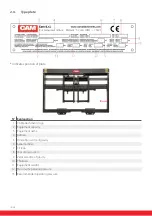
Page 7: ...of each product can be found in chapter 10 Annexes PL Series PL T Series N Description N Description W2 W3 Width of forks H10 Internal view space W4 Frame width ISO2328 FEM class W6 Minimum width of...

Page 8: ...8 36 2 2 Main components of the product N Component 1 Frame 2 Fork Supports 3 Fork Positioning Cylinders 4 Distribution Block 5 Hooks 6 Sideshifting Cylinder 7 Greasers...

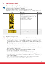
Page 9: ...damaged or missing replace them N Decal Explanation Ref 1 Brand decal Contact your dealer 2 1 Warning 2 Important carefully read the manual before using the equipment and carrying out the maintenance...

Page 10: ...attachments logo 2 Equipment capacity 3 Equipment name 4 Address 5 Horizontal centre of gravity 6 Serial number 7 CE logo 8 Year of production 9 Vertical centre of gravity 10 Thickness 11 Equipment we...

Page 11: ...all of the safety rules in force in the country of its use are applied to guarantee that the equipment is used in conformity with the use for which it is intended and to avoid any dangerous situation...

Page 12: ...he work CAM attachments cannot under any circumstances be held responsible for accidents or damage resulting from the use of the equipment by inadequately trained personnel or if inappropriate use has...

Page 13: ...lm to protect it from weather influences and corrosion during transport Adjust your driving speed while driving over rough terrain and up and down slopes Only transport the equipment in its lowest pos...

Page 14: ...n Before commissioning carry out a risk analysis of the assembly of the CAM attachment on the forklift Before using the equipment carefully read the instructions in the manual of your lifting device 5...

Page 15: ...e plate to confirm the weight of the attachment Select the appropriate materials according to the weight slings cables hooks etc Check the stability of the equipment before lifting Only use lifting de...

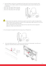
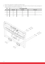
Page 16: ...equipment by raising the lifting device and reposition the two lower hooks securing them with the corresponding bolts indicated below Screw dimension Driving torque Nm 8 8 type 10 9 type 12 9 type M1...

Page 17: ...ule ensure that the distance is less than the 2mm shown In the event the distance exceeds 2mm the equipment must not be put in to service and you should contact your dealer for guidance 10 Flush suppl...

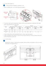
Page 18: ...s indicated in the table below and as stated on the type plate A flow rate less than recommended will result in a lower operating speed A flow rate greater than maximum can result in excesssive heatin...

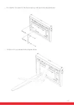
Page 19: ...19 36 Uninstall the shoulders of the fork pockets as indicated in the diagram below Fit forks on PL as indicated in the diagram below...

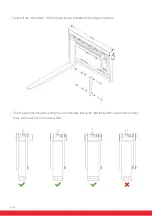
Page 20: ...nstall the shoulders of the fork pockets as indicated in the diagram below The PL attachment has the ability to accommodate forks with different width Add shims for wider forks remove shims for narrow...

Page 21: ...rew the nut to lock the pin 14 Synchronism regulation Unscrew slightly the nuts B on both L and R flow regulators Fully unscrew the pins A on both L and R flow regulators Operate at least five open an...

Page 22: ...ccording to the terrain Never lift or transport an unlocked attachment Do not use if there is a risk of unexpected movement only use the vehicle on solid surfaces Only operate the equipment from the o...

Page 23: ...form the daily maintenance check before each use as described in chapter 7 3 Maintenance instructions Before starting First use the hydraulic levers to check which levers operate which function Operat...

Page 24: ...ck up the load parallel to the floor Always use both forks 4 When moving your lifting device lift the load 200 mm from the ground If you are using a lift truck make sure you tilt the mast backwards Co...

Page 25: ...ised remove ignition key In the event of injuries caused by escaping oil under pressure immediately seek medical assistance Use Loctite 242 REF 126TA5184 on the screws to reinstall parts previously di...

Page 26: ...eaks Replace any damaged hydraulic hoses to prevent them from rupturing and causing any accidents Never try and search for leaks or plug a leak by hand Liquids under high pressure can easily penetrate...

Page 27: ...nt through five complete cycles First test without the load then test with a load to make sure the attachment operates correctly before returning to service 6 Lubrication Every 200 hours lubricate upp...

Page 28: ...Check the wear of the seals Every 2000 hours check the wear of the seals and replace them if necessary This may only be done by a qualified service technician and according to the manufacturer s instr...

Page 29: ...y but not with load No pressure from carriage Check the pressure coming from the fork lift and set it as indicated in the table in chapter 5 3 11 No oil arrives from the fork lift Check the fork lift...

Page 30: ...aging should be sorted and put into solid dustbins according to the materials and needs to be collected by the local special environment protection bureau To avoid pollution it s forbidden to throw aw...

Page 31: ...31 36 10 ANNEXES 10 1 CE certificate...

Page 32: ...32 36 10 2 Technical data PL series...

Page 33: ...33 36 10 2 Technical data PL T series...

Page 34: ...draulic Information As each attachment is individual please see chapter 5 3 11 for guidance on hydraulic connection The spare parts list included with the equipment contains an attachment specific hyd...

Page 35: ...o consult the CAM attachments website or to contact the supplier or dealer to obtain the correct revision On the equipment you can find attached a copy of the spare parts list and a copy of the user m...

Page 36: ...truction Industry Food beverage Paper handling Brabantstraat 15 8790 Waregem Belgium T 32 56 43 42 11 F 32 56 43 44 88 www camattachments com info camattachments com Your distributor MadeinItalyforTVH...

Reviews: