background image

ZXIMCU PT01 P200 Portable Emergency Command System Operation Manual

All rights reserved

© 2021 Copyright Caltta Technologies Co.,Ltd.

Page 39

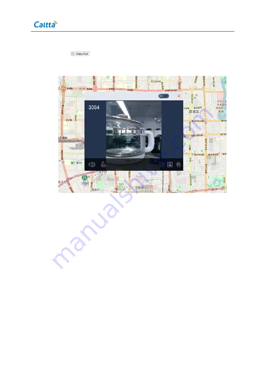
Click

to pull the video, see the following figure.

Figure 5- 43 Dispatching the terminal on the Map interface

6

Card Allocation and Number Allocation

6.1

Hand-held Terminal Number Allocation

6.1.1

Login to the unified OMM

Login to the unified OMM via IE browser (IE 11).
Login address: http://192.168.90.129:2323/inms_ 249/client/#
Login account: admin, password is null.
Note: Different projects may use different login IP addresses, accounts, and
passwords. For details, please refer to the project system configuration guide.

Summary of Contents for ZXIMCU PT01 P200

Page 1: ...ZXIMCU PT01 P200 Portable Emergency Command System Operation Manual ...

Page 2: ......

Page 3: ...formation owned by Caltta Technologies Co Ltd without the written permission of Caltta Technologies Co Ltd any unit or individual shall not use or leak any document and Figures this document contains tables Figure data and other information The information in this document contains the development progress of Caltta Technologies Co Ltd products and technology will continue to update Caltta Technol...

Page 4: ...SOLE INTERFACE INTRODUCTION 13 5 1 4 DISPATCH CONSOLE INITIATES A HALF DUPLEX VOICE PRIVATE CALL 19 5 1 5 DISPATCH CONSOLE INITIATES A FULL DUPLEX VOICE PRIVATE CALL 20 5 1 6 DISPATCH CONSOLE INITIATES A FULL DUPLEX VIDEO PRIVATE CALL 20 5 1 7 DISPATCH CONSOLE INITIATES A VOICE GROUP CALL 21 5 1 8 DISPATCH CONSOLE INITIATES A VIDEO GROUP CALL 21 5 1 9 SENDING SMS AND MMS 22 5 1 10 FORCED RELEASE A...

Page 5: ...N INFORMATION CONFIGURATION 40 6 1 3 USER NUMBER ALLOCATION 41 6 1 4 ADD GROUP 44 6 1 5 ADD GROUP MEMBER 45 6 2 CPE TERMINAL NUMBER ALLOCATION 47 6 2 1 LOGIN TO THE UNIFIED OMM 47 6 2 2 USER AUTHENTICATION INFORMATION CONFIGURATION 47 6 2 3 USER NUMBER ALLOCATION 48 6 2 4 LOGIN TO THE LTE CORE NETWORK MANAGEMENT PAGE 48 6 2 5 APN CONFIGURATION 49 6 2 6 SYNCHRONIZE DATA 51 6 2 7 SHOW CPE ACCESS STA...

Page 6: ...dispatch console 11 Figure 5 2 Selecting dispatch console local IP address 11 Figure 5 3 Login interface of the dispatch console 12 Figure 5 4 Dispatch console interface 13 Figure 5 5 Dispatch console interface layout 14 Figure 5 6 Add user to dispatching operation area 15 Figure 5 7 Remove user from dispatching operation area 15 Figure 5 8 Sound channel selection 16 Figure 5 9 User call attribute...

Page 7: ... MDS client logging 32 Figure 5 34 Operations of the multimedia dispatch video pull 33 Figure 5 35 Multimedia dispatch video display window 34 Figure 5 36 Multimedia dispatch video distribution 35 Figure 5 37 Video distribution is successful 35 Figure 5 38 Video is distributed to the receiving terminal 36 Figure 5 39 Ending video distribution 36 Figure 5 40 MDS terminal location operation 37 Figur...

Page 8: ...e CPE Authorization Profile 51 Figure 6 17 Show CPE access status 52 Figure 6 18 Add dispatcher account 52 Figure 6 19 Setting dispatcher account information 53 Figure 7 1 Trusted sits setting of the Internet Options 54 Figure 7 2 Security settings of trusted sites 1 55 Figure 7 3 Security settings of trusted sites 2 56 Figure 7 4 Security settings of trusted sites 3 56 Figure 7 5 Temporary Intern...

Page 9: ...d operation methods for MDS core network base station terminals and peripheral supporting products Please select the corresponding operation steps according to the actual system and device 2 ZXIMCU PT01 P200 Version 3 0 2 1 Introduction of ZXIMCU PT01 P200 Version 3 0 The distributed structure of control unit and RF unit helps P200 reduce its weight which is more convenient for carrying The System...

Page 10: ...nnecting with dispatch console or backhaul device 2 Handle convenient to carry 3 Network Interface 2 used for connecting with dispatch console or backhaul device 4 Optoelectronic Input Interface connect with RRU via power line 5 CPS Antenna Interface connect with GPS Antenna 6 System Debugging Interface 7 Extended Optical Fiber Interface Figure 2 2 ZXIMCU PT01 P200 RRU ...

Page 11: ...ut Interface power input and connect with MPU 2 RF Antenna Interface 3 Handle 4 RF Antenna Interface Figure 2 3 ZXIMCU PT01 P200 Power Line 1 A Connector Waterproof connector with large size diameter connect to RRU 2 B Connector Waterproof connector with small size diameter connect to MPU 3 C Connector Triangle plug connect to external power supply ...

Page 12: ...line to RRU connect B connector to MPU and tighten them up Figure 2 5 Connection between MPU and RRU with the the power line Step 3 Connect feeder and antenna Connect one end of the antenna feeders 2 pieces to the RF interface of RRU connect the other end to the RF antenna Make sure to tighten them up when connecting otherwise it may cause the weak signal and lead to failure of registration when t...

Page 13: ...ved 2021 Copyright Caltta Technologies Co Ltd Page 5 Step 4 Connect GPS Antenna no need to connect if the device is used as a stand alone station Connect one end of the GPS feeder to the GPS antenna interface of MPU the other end to the GPS antenna Figure 2 7 Connection of GPS antenna ...

Page 14: ...e main power switch is on the side of the RRU Observe the RRU indicators The RUN indicator flashes after power on the RUN and OPT1 indicator flash after the system starts normally and the ACT indicator is always on Figure 2 8 Power switch and indicator light Step 6 Use network cable to connect the dispatching laptop to any of the MPU network interface The network interface could also be used as ou...

Page 15: ... DSS multimedia dispatching server MDS base station system and terminals and provides end to end multimedia command and dispatch solution While providing kinds of multimedia service such as voice video and data the system can also support data bearer and transmission for the third party keeping the system in openness LTE Portable Emergency Command System network topology is shown as follows Figure...

Page 16: ...ing PC The PC operating system requires Win 7 or above 4 1 IP Address Setting The IP address of PC needs to interconnect with the IP address of MDS server defaults to 192 168 13 20 and the IP address of trunking dispatch console defaults to 192 168 13 21 Interconnecting to OMM IP address is also required while login the OMM system The following two IP addresses can be configured individually in th...

Page 17: ...ed Before logging in make sure the PC has been installed with Adobe flash player and the IE settings are correct otherwise the OMM interface may not open The Adobe flash player plug in and IE setting script can be downloaded and installed on the OMM interface Figure 4 2 Download plug in and script on the OMM interface Script setting of IE trusted site Extract the following compressed package or th...

Page 18: ...y key to exit when finishing set up 5 Trunking Services Operations 5 1 Operations of DAS Unified Dispatch Console 5 1 1 Dispatch Console Installation Install the dispatch console software on the PC in advance and login the DAS dispatch console via the CS client Input the defaulted IP address 192 168 13 21 in the IE browser then it will enter into the interface of plug in and client downloading Aft...

Page 19: ...f the dispatch console 5 1 2 Dispatch Console Login Double click the DAS dispatch console icon and open the software The DAS software will pop up the IP selection interface if the fixed IP address changes or for first time login Select 192 168 13 160 as the dispatch console local IP address Click OK to enter the login interface Figure 5 2 Selecting dispatch console local IP address ...

Page 20: ...then click Login to login in the dispatch console The defaulted parameters of the dispatch console are as follows Account number dis01 Password 666666 Server IP address IP address of the trunking dispatch console 192 168 13 21 MDS IP address 192 168 13 20 Tip 1 Modifying the Local IP Address of the Dispatch Console Enter to the login interface of the dispatch console after the local IP address is ...

Page 21: ... Page 13 2 Method 2 Modify the configuration file in the DAS software installation directory Change the local IP address by modifying the localIP 192 168 13 160 in the config ini file 5 1 3 Dispatch Console Interface Introduction The dispatch console interface is shown as follows after login Figure 5 4 Dispatch console interface ...

Page 22: ... Area 2 User list area which shows the authorized users of the system and user online status The hand held terminal means default fleet user individual device means camera user Click the icon on the upper right corner of user list to display or hide the user list Area 3 Toolbar and shortcut tools of trunking functions such as temporary group dynamic regroup emergency alarm etc Area 4 Function disp...

Page 23: ...list double click to add the user group dispatch console to the dispatching operation area Or right click and select Voice Dispatch to add the user group dispatch console to the dispatching operation area Figure 5 6 Add user to dispatching operation area Remove users from dispatching operation area Move cursor to the user to be removed right click and select Remove dispatch Figure 5 7 Remove user ...

Page 24: ...he corresponding channel can be selected as required By default balance channel is selected Figure 5 8 Sound channel selection User call attribute setting Move cursor to a user right click and select Call attribute from the shortcut menu Select the corresponding call attribute as required If select Full duplex the dispatch console will make a full duplex call with the user Otherwise it is a half d...

Page 25: ... 5 10 Group call attribute setting Dispatcher call attribute setting Move cursor to the dispatch console right click and select Call attribute from the shortcut menu to select the call attribute as required Figure 5 11 Dispatcher call attribute setting 5 1 3 3 General Operations of GIS Dispatch Select GIS from the menu display the map interface ...

Page 26: ...olling the mouse wheel drag the left mouse button to move the map and search for locations The toolbar is on middle top of the map which provides functions of Zoom in Zoom out Frame select Ranging Clean and so on 5 1 3 4 General Operations of Video Dispatch Select Video on the menu to display the video dispatching interface The upper part of the video dispatch area is the split screen control butt...

Page 27: ...oins the call the dispatch console has the floor and the terminal can hear the voice of the dispatch console During the call you can change the sound channel and choose whether to locally record the call Move cursor to the upper part of the terminal that is calling and click to release the floor or apply for the floor After dispatch console releases the floor the terminal can apply for the floor b...

Page 28: ...ringing and call is established Figure 5 15 Dispatch console initiates a full duplex voice private call 5 1 6 Dispatch Console Initiates a Full duplex Video Private Call Move cursor to the user Call attribute defaults to Full duplex and right click select Video calling the dispatch console and terminal will ring After the terminal answers the call the full duplex video call is established The vide...

Page 29: ... following figure shows the status of call origination call in progress before apply for after release the floor Figure 5 17 Dispatch console initiates a voice group call 5 1 8 Dispatch console initiates a video group call Move cursor to a group right click and select Video group call the terminal will automatically answer the call and establish a group video call Video will be displayed in the lo...

Page 30: ...from the shortcut menu to send SMS and MMS to the terminal Multiple file formats are supported up to 20 MB Group operation is also supported Right click a group to send SMS and MMS to the online group members Figure 5 19 Sending SMS and MMS 5 1 10 Forced Release and Forced Insertion by the Dispatcher Forced Release The dispatcher can forcibly release a private call or a group call in progress When...

Page 31: ...he call activation list on the dispatch console will display the ongoing group call Select an ongoing group call and click to insert the call The group will be automatically added to the dispatch area and the dispatch console obtains the floor Figure 5 21 Forced insertion by dispatcher 5 1 11 Dynamic Regroup The dispatch console can dynamically regroup users based on the target group and add users...

Page 32: ... The group will disappear when it is removed from the dispatch area To the contrary the group information of the dynamic group will be saved and can be dispatched later Click on the toolbar of the dispatch console to open the temporary group interface Input a temporary group name and double click the user to be added from the user list To remove a dynamic member click on the right side of the memb...

Page 33: ...inals in the group The dispatch console can display the information of the user who initiates an emergency call and the time when the user initiates the call The dispatcher can click to intervene the emergency call and switch to voice group call and contact the user or other group members for proper handling Figure 5 24 Emergency call 5 1 14 Dispatch Console Location Select GIS from the system men...

Page 34: ...oning Figure 5 25 Dispatch console location operation The location is successful if the terminal information is shown on the map Move cursor to a terminal on the map the detailed location information will be displayed in the following red box 1 Click a terminal to dispatch it on the map as the following red box 2 Click to end the location Click to display the moving path of the terminal Click to p...

Page 35: ...nologies Co Ltd Page 27 Figure 5 26 Map interface display and operation 5 1 15 Frame Select and Dispatch on the Map Frame select terminals on the map to make a temporary group call Figure 5 27 Frame select on the map Tick the terminals in the pop up box that need to be called and click Call to start the group call ...

Page 36: ... then switch to the Video Dispatch interface Move cursor to a user the user will be highlighted Right click the user to display the operation menu Select Video Pull the terminal video can be pulled to the dispatch console the setting of the terminal video dispatch is configured correctly and registered successfully If auto Rcv Push is not ticked in terminal video dispatch setting the video will be...

Page 37: ...terminal videos to be displayed on the upper area of the Video interface Click to customize the display mode Move cursor to the toolbar on the bottom of video display window click to end the Video Pull Click to capture the video image Click to capture the video images continuously Click to record video Click to distribute the terminal videos Click and to control the speaker and microphone of the t...

Page 38: ... video to the dispatch console first and then move cursor to the video display window the toolbar will be shown Click at the video s bottom right corner to open the Video forward and distribute page Select the users who need to receive video the users should be registered online from the user list and click Start Distribution on the page to distribute the pulled video to the specified terminals Th...

Page 39: ...tions of Multimedia Dispatch System The Multimedia Dispatch System MDS client supports independent client operations It s required to install the client before logging Install the CS dispatch console client on the dispatching PC Click the installation file then click Next until the installation is completed as shown in the following figure Figure 5 32 Client Installation of the Multimedia Dispatch...

Page 40: ...ce then configure the IP address of the server as the following figure IP address of the server the account and passwords default settings are as follows Server IP address 192 168 13 20 Account password 88807558001 666666 consistent with the OMM account information in the authentication configuration Figure 5 33 MDS client logging 5 2 2 Video Pull The dispatch console can pull video from cameras a...

Page 41: ...orner of the video window to lock the video angle Click at the lower right corner of the video window to automatically rotate the terminal video that is the video on the dispatch console is rotated when the terminal rotates Click at the lower right corner of the video window to capture the video image Click at the lower right corner of the video window to capture continuous video images Click at t...

Page 42: ...deo display window 5 2 3 Video Distribution Dispatch console can distribute the pulled videos to terminals and groups Select a video that has been pulled on the interface of the dispatch console click on the lower right corner of the window then the distribution page will pop up Add the users who need to receive the videos to the distribution page as the following figure ...

Page 43: ...5 Figure 5 36 Multimedia dispatch video distribution Click Start Distribution to distribute the video For example after a video is successfully distributed to user 5903 the pull and distribution status will be displayed on both the user list and the distribution list See the following figure Figure 5 37 Video distribution is successful ...

Page 44: ...low Figure 5 38 Video is distributed to the receiving terminal Click End on the Terminal who is receiving video to end the video distribution Or select the terminal that is distributing videos on the video distribution page of the dispatch console and click End Distribution to end the video distribution see the following figure When ending the pulled video source the video distribution ends at the...

Page 45: ...ps can be located at the Map interface of the dispatch console Select the terminal to be located and select Location from the shortcut menu see the following figure Figure 5 40 MDS terminal location operation As shown in the above figure the location of the terminal is displayed clearly on the map When moving cursor to the terminal the terminal details will be displayed ...

Page 46: ...gure 5 41 MDS location display Right click the contact list of the terminal and select to view the historical track replay of the terminal as the following figure Figure 5 42 Viewing historical track of the terminal Input the Start time and End time on the Historical Track page and click Search to query the historical track of the terminal ...

Page 47: ...l on the Map interface 6 Card Allocation and Number Allocation 6 1 Hand held Terminal Number Allocation 6 1 1 Login to the unified OMM Login to the unified OMM via IE browser IE 11 Login address http 192 168 90 129 2323 inms_ 249 client Login account admin password is null Note Different projects may use different login IP addresses accounts and passwords For details please refer to the project sy...

Page 48: ...hts reserved Figure 6 1 Unified OMM interface 6 1 2 User Authentication Information Configuration Step1 Click Operation Management select Authentication and switch to the Authentication information interface Select Add card under the menu to add the user authentication information see the following figure Figure 6 2 Add card ...

Page 49: ...ain and OPC can directly copy the existing card information on the Add card page Click Save to complete operation as the following figure Figure 6 3 Input Add card information Note Select the user authentication information to be operated click and to edit or delete the information 6 1 3 User Number Allocation Step 1 Click Operation Management User and switch to the user management interface and s...

Page 50: ...mber beginning with 1880755 tick Activated data service select iepc com as the data service template tick Subscribed PTT service input Fleet user number recommend the last four digits of IMSI and User name and select Belonged fleet by clicking on the right for the user For a vehicle mounted terminal tick Vehicle mounted terminal option Keep the default settings for other parameters and click Save ...

Page 51: ...and System Operation Manual All rights reserved 2021 Copyright Caltta Technologies Co Ltd Page 43 Figure 6 5 Input user information 1 Figure 6 6 Input user information 2 Note Select the user to be operated click and to edit or delete the user ...

Page 52: ...and switch to the Group management interface and select ZiLTE group under menu on the right to add group Figure 6 7 Add group Step 2 Input Group number beginning with 6880755 Group short number and Group name on the Add group interface Select default fleet by clicking the on the right for the Belonged fleet Keep the default settings for other parameters and click Save see the following figure ...

Page 53: ...ologies Co Ltd Page 45 Figure 6 8 Group account information setting Note Select the group to be operated click and to edit or delete the group 6 1 5 Add group member Select the group that need to add group members and click the number in the Group member column see the following figure Figure 6 9 Add group member 1 ...

Page 54: ...display the page for editing group members see the following figure Figure 6 10 Add group member 2 Select the member to be added from the available members list and click to add the group member see the following figure Figure 6 11 Add group member 3 Note Support add or delete multiple group members Note Select the users to be deleted from the right side and click to delete the member ...

Page 55: ...o the unified OMM via IE browser IE 11 Login address http 192 168 90 129 2323 inms_ 249 client Login account admin password is null 6 2 2 User Authentication Information Configuration User authentication information is configured in exactly the same way as described in chapter 5 1 2 Step1 Click Authentication and switch to the Authentication information interface Select Add card under menu on the ...

Page 56: ...e Data service template Keep the default settings for other parameters and click Save to add a CPE user information see the following figure Figure 6 13 Input user information Note Select the user to be operated click and to edit or delete the user 6 2 4 Login to the LTE Core Network Management Page Login to the OMM management page of the iEPC LTE core network via Web Login address http 192 168 90...

Page 57: ...E Access Terminal IP Pool Configuration Show CPE IP Pool and click the system will display all IP pool configuration information Select Create CPE IP Pool to add a CPE IP pool Input the information and click to execute CPE pool ID Number of the address pool which must be unique VRF ID Defaults to 0 Select Add CPE IP Segment and add the IP segment information to the corresponding IP pool Input the ...

Page 58: ... from the menu on the left Daily Maintaining APN Configuration CPE Terminal Authorization Profile Configuration Show CPE authorization Profile and click the system will display all CPE authorization Profile configuration information Select Create CPE Authorization Profile and add the CPE authorization information Input corresponding information and click to execute Profile ID The same as the Profi...

Page 59: ...e Perform Show CPE authorization Profile again to check whether it is added successfully 6 2 6 Synchronize Data Synchronize related data to the system after completing the above steps Select from the menu on the left Daily Maintaining Data Transfer Synchronize EPC Data click and select Yes on the pop up dialog box to complete the configuration data synchronization Or directly input SYNC EPC in the...

Page 60: ...tta Technologies Co Ltd All rights reserved Figure 6 17 Show CPE access status 6 3 Dispatcher Management Step1 Select Operation Management Dispatcher switch to the dispatcher management interface Click on the right side to show interface of adding a dispatcher Figure 6 18 Add dispatcher account ...

Page 61: ... corresponding information according to the interface requirements the dispatcher number beginning with 8880755 11 digits and click Save at the bottom to complete the operation of adding a dispatcher see the following figure Figure 6 19 Setting dispatcher account information Select the dispatcher to be operated click and to edit or delete the dispatcher ...

Page 62: ...patch console please check whether the IE settings have been modified Open the IE browser and select Tools Internet Options from the toolbar open the Internet Options dialog box Select Security Trusted sites Sites open the Trusted sites page see the following figure Add the IP address of the dispatch console to the trusted site For example take the IP address of the dispatch console as 192 168 90 ...

Page 63: ...ons Security select Trusted sites and click Custom level to enter the Security Settings Trusted Sites Zone page to set the security level of the trusted sites Set all the sub items under ActiveX controls and plug ins to Enable see the following figures Figure 7 2 Security settings of trusted sites 1 Set all the sub items under Downloads to Enable see the following figures ...

Page 64: ...nual Page 56 2021 Copyright Caltta Technologies Co Ltd All rights reserved Figure 7 3 Security settings of trusted sites 2 Select Enable for Allow script initiated windows without size or position constraints click OK Figure 7 4 Security settings of trusted sites 3 ...

Page 65: ...td Page 57 Return to the page of Internet Options General and click Settings to enter the Temporary Internet Files page Select Every time I visit the webpage OK see the following figure Figure 7 5 Temporary Internet Files Settings Switch to the page of Internet Options Privacy and remove the check mark of Turn on Pop up Blocker ...

Page 66: ...stem Operation Manual Page 58 2021 Copyright Caltta Technologies Co Ltd All rights reserved Figure 7 6 Uncheck Turn on Pop up Blocker Switch to the page of the Internet Options Advanced tick Use software rendering instead of GPU rendering click OK ...

Page 67: ... Operation Manual All rights reserved 2021 Copyright Caltta Technologies Co Ltd Page 59 Figure 7 7 Advanced Setting of Internet Option Restart the IE browser to validate the configuration 7 2 Appendix A 1 1 7 2 1 Appendix A 1 1 1 Attention Precautions ...

Reviews: