background image

1

2


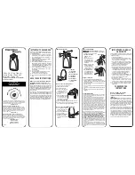
Connecting Additional Remote Controls

Figure 15 

There are two ways to connect your remote control: Study Mode & Numeric Mode. 

Study mode can fit up to 60 different remote controls. 

Connect using Study Mode On your gate operator circuit board, look for the study key. Press 
and hold the button on the remote control. Press and hold the study key for 1.5-2 seconds. 
Done, the remote is now connected to the gate opener.

Removing  existing  remote  controls Press  the  STUDY  key  on  the  gate  operator  circuit 
board and hold for 8 seconds. Done. All remote controls are now removed.

Numeric Mode 

A.  On your circuit board, turn the SW9 key to the ON position.

B. Unscrew  the  back  of  the  remote  control  to  gain  access  to  the  control  board.  You 
should  see  1-8  dip  switches.  Each  switch  has  3  positions:  up,  middle,  bottom.  Flip 
these  1-8  switches  to  any  position  you'd  like.

C. On the gate opener control board, look for the same 1-8 dip switches, and set the same 
combination as you did on the remote.

D. Finished.

Note: On  switch  SW10,  KEY  1  and  KEY  2  are  used  for the 2-button  model  of  remote 
controls. Note: if KEY 1 code was set with BUTTON ONE on remote control; KEY 1 will NOT 
work with BUTTON TWO on the remote control. 

Features

By default, the remote controls are already connected to the gate operator. You do not need to 

do any of the following steps unless you are adding more remote controls.

Study Mode

Youtube 

Youtube video that explains more on remote control programming: 

https://youtu.be/QfT6O4apTI8

Summary of Contents for CM3-DCFP

Page 1: ...www calimetco com 9949 Hayward Way South El Monte CA 91733 Tel 626 452 9009 Sliding Gate Operator 24V Battery Backup CM3 DCFP Instruction Manual...

Page 2: ...d Read the owner s manual on how to maintain your gate Have a certified service technician make repairs or install gate operator hardware The gate entrance should be used for vehicles only Pedestrians...

Page 3: ...tes Primary Device A B1 B2 D Secondary Device one required A B1 B2 D E Swing Gates Primary Device A B1 B2 C D Secondary Device one required A B1 B2 C D E REQUIRED ENTRAPMENT PROTECTION A Inherent buil...

Page 4: ...gate while operating the controls Controls intended to be used to reset an operator after 2 sequential activations of the entrapment protection device or devices must be located in the line of sight...

Page 5: ...either the Front or Rear Position If you re not sure choose the Front position Front Position Rear Position or If you chose Rear Position install the chain using figure 2 Install the operator INSIDE...

Page 6: ...5 Figure 3 Figure4 Installation The gate operator should be 5 inches away from the gate The chain should be 5 inches above the base Gate Operator Distance from Gate and Base...

Page 7: ...6 Installation Contact local underground utility locating companies before digging more than 12 inches deep to avoid damaging underground power gas or other utility lines Wedge Anchor Size of concrete...

Page 8: ...ch 2 5 cm of sag for every 10 feet 3m of chain length Chain should not be too tight or too loose Chain should be straight and not bent at an angle If the chain is too loose remove links from the chain...

Page 9: ...ted circuit for power supply 3 When the power is connected turn the power switch to the ON position Installation Step 4 Connecting the Power Power Battery See which direction your gate opens when view...

Page 10: ...our gate about 21 from the ground 4 Press the orange button on the photo eye to turn on the infrared beam 5 Mount the reflector to the opposite side Make sure the infrared beam hits inside the circle...

Page 11: ...tment section is located inside the gate opener Youtube More detail on travel limit programming https youtu be _DeVM5dgZPs Push the metal lock back in when done Push and hold the metal lock back and t...

Page 12: ...Reset the pedal only when the operator doesn t work while using the remote control 1 Push the pedal downward from locked position and slightly move to the left 2 Allow the pedal rise up to the reset p...

Page 13: ...on B Unscrew the back of the remote control to gain access to the control board You should see 1 8 dip switches Each switch has 3 positions up middle bottom Flip these 1 8 switches to any position you...

Page 14: ...om of the circuit board with the words DATA and DATA B Use a flathead screwdriver to release the 2 locks on the top of the green terminal C For conductor 1 connect the DATA on the MASTER circuit board...

Page 15: ...14 Figure 16 Features Safety and Exit Loop This is an optional step If you wish to install a exit loop detector see figure 16 for the position of the safety and exit loops Entrapment Protection...

Page 16: ...15 Features Control Board Layout This is a picture of the control board Use this for reference Youtube Circuit board Programming Guide https youtu be _7iBuKr1ZtY...

Page 17: ...to move gate to opposite direction Features DIP Switch Features There are 6 dip switches located at the bottom of the circuit board Each switch has a different feature 4 1 PASS Anti tailgating system...

Page 18: ...nsors Figure18 Follow infrared control instructions to connect power Common wire is connected to Common pole signal wire is connected to OPEN or CLOSE pole Note Check Photo eye connection if hear a lo...

Page 19: ...18 Features Installing an External Receiver External connectors are installed on the rear side of mainboard protector box Figure19...

Page 20: ...n causing the gate to reverse The open and close knobs determine the amount of force required to reverse the gate figure 21 We generally recommend leaving the knob at 75 or around a 3 00 position You...

Page 21: ...6 seconds by turning knob on DELAY 1 On your gate operator circuit board in the bottom turn Dip Switch 2 to the ON position Figure 22 2 On the gate operator circuit board adjust the delay by turning t...

Page 22: ...1 Other 1 BAT 24V external Battery Connector 2 LOOP DETECTOR Only compatible with Calimet Loop detector device 3 RELAY 1 Signal light connector this light only turns on when door is in motion Features...

Page 23: ...N when STAND BY blinks when motor is on 11 B L POWER ON when back up battery is fully charged blinks when low battery 12 M S LINK Blinks when master slave communication is active 13 TIMER Blinks when...

Page 24: ...9949 Hayward Way South El Monte CA 91733 Tel 626 452 9009 Alternate 626 482 3066 Fax 626 452 9010 Email info calimetco com www calimetco com...

Reviews: