S320 OCS Hardware User Guide
Doc. Part No. 460167-00
May 27, 2015
Rev. B7
Page 28 of 46
3.3.4.2
Version 2
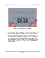
Management interfaces on version 2 of the switch (Figure 9) include:
Two (2) Gigabit Ethernet (GbE) RJ45 connectors, labeled LAN A and LAN B. These
interfaces are arranged horizontally and located to the left of the external alarm
interface.
One (1) RJ45 connector—labeled SERIAL PORT—is located to the right of the external
alarm interface.
Please refer to CALIENT’s
Optical Circuit Switch (OCS) TL1 Reference Guide
and
Software
Application Interfaces Guide
for detailed information on managing the S320 OCS.
3.3.5
Power Source Interfaces
The S320 OCS is powered by redundant power source inputs: Power Source A and Power
Source B. Each input holds a single -48 VDC power module. If Power Source A fails, the system
automatically draws all required power from backup Power Source B without affecting existing
cross-connections or management connectivity.
LEDs indicating power source status are located on the front panel of the switch (see section
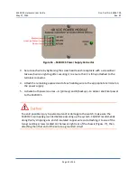
3.3.2). In addition, each power module has an LED located at the right of the module faceplate
(Figure 10 and Figure 11) that indicates whether the module is on (LED is lit) or off (LED is unlit).
Version 1 power modules also have a Reset button located at the right of the LED; pressing this
button repowers the system if an emergency shutdown has occurred.
Figure 10 – S320 OCS Power Module (Version 1)
Reset button


