background image

14

LP GAS HOOKUP

LP GAS HOOK UP:


(TYPE 1 OR QCC1 REGULATOR):

Grills orifices for use with LP gas come equipped with a high capacity hose/regulator assembly for connection to

a standard 20 lb. LP cylinder (Type 1). The LP tank is not included.

Connection:

1/2” NPT male with a 3/8” Flare adapter (included). LP Hose with a quick disconnect and fittings are

included. Operating pressure: 11.0” W.C.


CAUTION!

Before connecting LP tank to regulator, check that all grill burners valves are in the OFF position and open grill lid.

To connect the LP regulator/hose assembly to the tank/valve assembly, first make sure the main valve on the tank 

is completely closed. Although the flow of gas is stopped when the Type 1 system is disconnected as part of its 

safety feature, you should always turn off the LP tank main valve after each use and during transport of the tank or 

unit. Insert the regulator inlet into the tank valve and turn to the black coupler clockwise until the coupler tightens 

up. Do not overtighten the coupler. Turn the main tank valve on and turn the burner control valves on the unit to 

the “HI” position for about 20 seconds to allow the air in the system to purge, turn valves off and wait 5 minutes 

before attempting to light the burners.

To disconnect the coupler, first make sure the main tank valve is turned off. Grasp the coupler and turn counter 

clockwise. The inlet will then disengage. Remove the inlet from the tank valve opening if it has not already done so 

when it disengaged. Your local LP filling station should be equipped with the proper equipment to fill your tank.

LP TANK REQUIREMENTS:

A dented or rusty LP tank may be hazardous and should be checked by your LP supplier. The cylinder that is used 

must have a collar to protect the cylinder valve. Never use a cylinder with a damaged valve. Always check for leaks 

after every LP tank change. The LP gas cylinder must be constructed and marked in accordance with the specifica-

tions for LP gas cylinders of the U.S. Department of Transportation (DOT or CAN/CSA-B339) and designed 

for use with a Type 1 system only. Do not change the regulator/hose assembly from that supplied with the unit or 

attempt to use a Type 1 equipped regulator/hose assembly with a standard 510 POL tank/valve assembly. The cyl-

inder must be provided with a shut-off valve terminating in an LP gas supply cylinder valve outlet specified, as ap-

plicable, for connection Type 1. If the appliance is stored indoors, the cylinder must be disconnected and removed 

from the appliance. Cylinders must be stored outdoors in a well-ventilated area out of the reach of children.

*Installation must conform with local codes or with the National Fuel Gas Code ANSI Z223.1 or the CAN/CGA-

B149.2 Propane Installation Code

NATURAL GAS HOOK UP


(THIS TYPE OF CONNECTION SHOULD BE PERFORMED BY A CERTIFIED OR LICENSED TECHNI-

CIAN ONLY.)

Connection: 1/2” NPT male with 3/8” flare adapter. Operating pressure: 4.0” W.C. Supply pressure: 5” to 14” 

water column. If in excess of 14” W.C., a step down regulators required. Check with your local gas utility company 

or local codes for instructions on installing gas supply lines. Be sure to check on type and size of run, and how deep 

to bury the line. If the gas line is too small, the grill will not function properly. Any joint sealant used must be an 

approved type and be resistive to the actions of LP gases.

TO HOOK-UP THE FITTINGS SUPPLIED WITH THE GRILL:

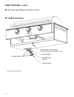
Assemble and leak test as shown in the previous pages illustrations. Use threading compound on male threads only. 

Do not use threading compound on the male end of the 1/2 NPT to 3/8 flare adapter. Use a second pipe wrench 

to hold the grill inlet pipe to avoid shifting any internal gas lines of the grill. Ensure that the regulator arrow points 

in the direction of gas flow towards the unit, away from the supply. Do not forget to place the installer-supplied gas 

valve in an accessible location.

Summary of Contents for Rockwell CRG48SS-L

Page 1: ...as hard piping required by certified installer 42 2 BURNER BUILT IN GRILL Model CRG42SS L 2 20 000 BTU Caliber Crossflame grill burners with Stainless Steel 42 base for use with built in projects usin...

Page 2: ...nding a leak is not a do it yourself procedure Some leaks can only be found with the burner control in the ON position and this must be done by a qualified technician Never attach or disconnect an LP...

Page 3: ...25 Page 26 Page 27 Care and Safety Precautions Grill Placement and Installation Pressure Testing and Hookups LP Gas Hookup Natural Gas Hookup Gas Requirements Air Shutter Adjustments Leak Testing Debr...

Page 4: ...y prac tices must be followed including but not restricted to the following FIRST Read entire Use and Care Manual carefully and completely BEFORE using your grill for the first time to reduce the risk...

Page 5: ...t use the grill to cook excessively fatty meats or products that promote flare ups COMBUSTIBLES AND LOCATION Do not operate the grill under unprotected combustible construction Use only in well ventil...

Page 6: ...ning or stirring food For proper lighting and performance of the burners keep the ports clean It is necessary to clean periodically for optimum performance Clean the grill with caution Avoid steam bur...

Page 7: ...ING The Burning of gas cooking fuel generates some by products which are on the list of substances which are known by the State of California to cause cancer or reproductive harm California law requir...

Page 8: ...struction is required to allow for movement around the entire perimeter of the grill It is desirable to allow at least 18 24 rear and side clearance to non combustible construction on all 4 sides of t...

Page 9: ...windy conditions can disrupt the proper flow of air though your grill leading to reduced performance or in certain severe cases causing heat buildup in the valve panel area This can lead to problems s...

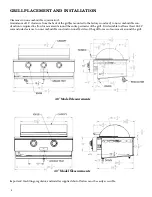
Page 10: ...10 42 Rockwell by Caliber Specifications 48 Rockwell by Caliber Specifications GRILL PLACEMENT AND INSTALLATION cont d...

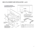
Page 11: ...11 GRILL PLACEMENT AND INSTALLATION cont d...

Page 12: ...not use threading compound on the male end of 1 2 NPT to 3 8 flare adaptor Use second pipe wrench to hold the grill inlet pipe to avoid shifting any internal gas lines of the grill Ensure that the re...

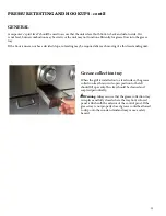
Page 13: ...uired after each moving of a this freestanding unit Grease collection tray When the grill is installed onto a level surface the grease collection tray shown in its open position to the left should fil...

Page 14: ...hange The LP gas cylinder must be constructed and marked in accordance with the specifica tions for LP gas cylinders of the U S Department of Transportation DOT or CAN CSA B339 and designed for use wi...

Page 15: ...uld be made by a qualified technician and in accordance with local codes and ordinances In the absence of local codes the installation must comply with the National Fuel Gas Code ANSI Z223 1 Gas conve...

Page 16: ...he burner Loosen the lock screw of the air shutter Make certain that the burners are sitting properly around the orifices and then light the burners WARNING If the burner is not sitting around the ori...

Page 17: ...ck the hose regulator and connectors for damage before each use Look for cracks abrasions brittleness holes dents and nicks Do not attempt to remove repair or replace the Regulator Hose assembly by yo...

Page 18: ...s supply fittings for leaks before each use 48 Grill Natural Gas Leak test points Leak test points Leak test points NG safety shut off valve Water Debris Cleanout Drain See Debris Cleanout and Hookup...

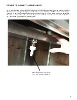
Page 19: ...s leaves etc which may enter the open area around the pe rimeter of the lid When installed with access doors just below the grill you will be able to clean out debris from the front as shown in pictur...

Page 20: ...re hose not included may be hard plumbed into a drain or with an installer supplied flexible 1 2 hose to drain to a location away from the front of the built in island See additional views of water de...

Page 21: ...g system and should be locked in place with its retaining bracket as shown below Please assure that all grill burner components are in place before you grill middle radiant not in place below Note The...

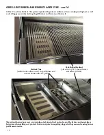
Page 22: ...below it The radiant shown above rests on 4 stainless steel pins in the front and rear of the firebox and must always be in place when grilling as it protects the burner ports from getting clogged wi...

Page 23: ...Push in and turn the desired burner control knob counter clockwise to the left HI posi tion As you turn the knob you will hear a click of the igniter If you do not see the burner ignite when turning...

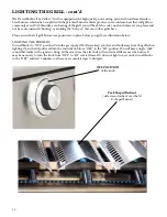
Page 24: ...ents are in place before you grill see illustration below LIGHTING THE BURNERS Turn all knobs to OFF position Turn the gas supply ON Always keep your face and body away from the grill when lighting Op...

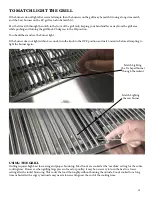
Page 25: ...onds turn the knob to the OFF position and wait 5 minutes before attempting to light the burner again Match Lighting the sear burner USING THE GRILL Grilling requires high heat for searing and proper...

Page 26: ...ition Extreme care should be used when removing any burner for cleaning The burner should be replaced correctly onto the orifice before any attempt is made to relight the grill IMPORTANT Make sure the...

Page 27: ...warranties expressed or implied and all other obligations or liability in connection with the sale of this appliance Caliber WILL NOT PAY FOR THE FOLLOWING Installation or start up Shipping damage Ser...

Page 28: ...any product specifications All material contained herein may not be reproduced without prior written consent of Caliber Appliances Copyright 2019 Caliber Appliances 17812 Metzler Lane Huntington Beac...

Reviews: