CALEFFI SATK32107 Series Instructions Manual Download Page 9

9

A

B

C

N.B.

 during the procedures for venting/draining the system use 

suitable measures to avoid the risk of any liquid dripping onto the 
electronic components.

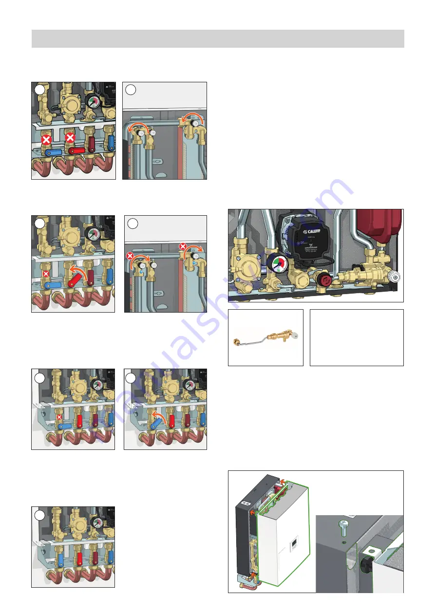
Vessel pre-charge check

Perform the following steps:
-   Use a pressure gauge to check the pre-charge value
-   If necessary, restore the pre-charge value shown in the technical 

specifications.

Filling the user system

SATK32 series HIU can be fitted with a charging unit equipped with a 
backflow preventer (F), check valve (E) and cock (G) (code 572120).
When filling the system for the first time or for subsequent top-up 
procedures following a heating circuit pressure switch fault, restore the 
system pressure (0,12–0,2 MPa - 1,2–2 bar) by opening cock (G) and 
checking the value by means of the pressure gauge (D).
Once the correct pressure has been reached, close the cock (G), 
vent the system and re-check the pressure (repeat the filling process 
if necessary).

System start-up

Before starting the HIU, visually check the hydraulic connections for 
the absence of any leakage and all the electric connections. After 
finishing the check, activate the electric supply to the HIU and check 
for the presence of any error signal.
If there is any, eliminate the fault indicated (see page 18) and proceed 
with setting the set point of the domestic water and heating cycles, 
programming the remote user interface according to the desired 
temperatures and times, and checking the operating cycles.

Commissioning

Fitting the cover

Fit the cover on the HIU by inserting the pins (A) in the locations 
provided (B).
Secure the cover by tightening the 4 screws provided (C).

Filling procedure for SATK32 centralised system

1. Open the air vent cocks upstream of the DHW and HEAT 

regulating valves.

2.  Slowly open the primary circuit flow shut-off valve at the HIU inlet. 

At this stage, shut off the air vent cocks when water begins to 

come out (fig. 2b).

3. When filling is complete, 

slowly open the primary circuit 

shut-off valve at the HIU inlet 

until it is fully open.

4. Slowly open the primary 

circuit return shut-off valve at 

the HIU outlet.

5. When filling is complete, 

slowly open the primary 

circuit return shut-off valve at 

the HIU outlet until it is fully 

open.

1a

1b

2a

2b

3

4

5

G

E

F

D

* Filling unit not used in the UK 
market. For information on the 
user system filling procedure, 
please refer to the technical 
documentation for the product 
ALT-HIUFLP in compliance 
with regulation G24 PTII.

Summary of Contents for SATK32107 Series

Page 1: ...stallation 5 Hydraulic components and diagram 4 Dimensions Technical specifications 3 Safety instructions 2 DHW function Comfort functions Primary flow rate limitation Circulator curves and setting Au...

Page 2: ...lled and in compliance with current legislation 5 The device must always be earthed before it is connected to the electric supply If the device must be removed always disconnect the earth connection a...

Page 3: ...nimum flow rate to activate domestic water flow meter 2 l min 0 3 Electric supply 230 V AC 10 50Hz Max power consumption 80 W Protection class IP 40 Pump UPM3 15 70 Actuators 24 V stepper motor Probes...

Page 4: ...9 Return temperature probe 10 Pressure gauge 11 Safety thermostat 12 130 mm heat meter template 13 1 4 F pressure test port 14 Connection for M10x1 heat meter return probe 15 Primary drain cock 16 Con...

Page 5: ...aulic installation Preliminary operations installation without template After having established the point of installation of the appliance perform the following operations Mark the holes required for...

Page 6: ...m in order to remove any residue or impurities that could endanger correct operation of the HIU In order to facilitate these operations a manual bypass flushing valve is available code 789110 N B In t...

Page 7: ...pipe To tighten the nuts apply maximum tightening torque of 25 Nm taking account of the indications of the heat meter manufacturer install the flow probe in the M10 pocket B Please refer to the heat m...

Page 8: ...ctric supply Remote user interface connection The HIU user interface has the dual function of control device and room thermostat The remote user interface can be installed on board the HIU or in the r...

Page 9: ...to the HIU and check for the presence of any error signal If there is any eliminate the fault indicated see page 18 and proceed with setting the set point of the domestic water and heating cycles pro...

Page 10: ...rature compensation day night Daytime night time setting temp Temperature display ambient set point probes prog Heating hourly programming and comfort function reset Resettable error reset floor slab...

Page 11: ...on day night Daytime night time setting temp Temperature display ambient set point probes prog Heating hourly programming and comfort function reset Resettable error reset floor slab heating function...

Page 12: ...e the modulating valve is opened gradually until the set point temperature is reached if the return temperature is lower than or equal to the set limit value In case this condition is not met the flow...

Page 13: ...es is 42 60 C while the range of possible return temperatures is 15 45 C if these set points cannot be changed you must set parameter t07 to value 0 in the technical menu see access to technical menu...

Page 14: ...DHW production The flow rate limitation is imposed by controlling the maximum opening of the primary circuit modulating valve Since latter is controlled by a differential pressure limiter it is possib...

Page 15: ...two seconds and then press the same key repeatedly until reaching the required characteristic refer to the figure below Having identified the required characteristic head flow rate chart shown below w...

Page 16: ...ow pump normally OFF The contact must be closed if any HIU function is active DHW production heating pre heating Parameter t05 must be set to 1 2 4 7 This value t05 7 is set by default example 2 Disti...

Page 17: ...ire twisted cable Compliance with this requirement becomes even more significant the more extensive the RS 485 network If alternatively a shielded wire is used the shield must be connected solely on t...

Page 18: ...m an external device indicating zero credit Corrective action Check the electrical connections or in the case of zero credit top up the external device contact the service supplier Heat interface unit...

Page 19: ...RT OTS RT PREPAID AUX RS 485 BUS IN IN IN OUT T ORT OTS RT PREPAID AUX RS 485 BUS IN IN IN OUT T LAVORATI ANGOLI 30 TOLLERANZA GENERALE ANGOLI EXP PORT OTS RT PREPAID AUX RS 485 BUS IN IN IN OUT IN OU...

Page 20: ...ween 0 9 and 1 2 bar Restore the pressure value if necessary Re open the shut off valves and restore secondary circuit pressure to a value between 1 3 and 1 7 bar Check for the absence of any liquid d...

Page 21: ...tuator see previous paragraph Extract the obturator unscrewing the locking nut F Replace the obturator screw on the locking nut F and then fit the actuator Insert the fixing clip respecting the correc...

Page 22: ...ature set point disable the function primary circuit strainer of the HIU clogged call qualified personnel to have it serviced exchanger partly clogged call qualified personnel to have it serviced modu...

Page 23: ...in charge of system electronic regulator not working call qualified personnel to have it replaced primary circuit flow rate insufficient contact person in charge of system centralised system not worki...

Page 24: ...ernal sensor prepayment auxilliary microswitch Modbus if required been carried out 15 Has the remote user interface been configured for installation on board thermostat function disabled inside the ap...

Reviews: