38
Heater Filament Power Cables
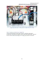
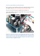
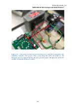
Connect the 6.3V and 0V from the power transformer secondary [Sec2: 2A] to the
[H1] and [H2] filament power supply PCB as shown in Figure 30. This is powering
the heater filament supply board.
The output from the filament power supply board is 6.3VDC which we will shortly
connect to the heater filaments on the amplifier board.
Figure 30 – Twisted cables (red and black) connecting power transformer
secondary terminals [6.3V, 0V] to the filament power supply PCB [AC +/- IN]
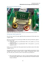
Now we will supply the heater filaments [H1] and [H2] on the amplifier boards
with the 6.3VDC from the heater filament power supply board.
The setup will be as follows:
•
Two pairs of cables will come out from the heater supply board (0V and
+V)
•
Each pair goes to [H1] and [H2] terminals on the amplifier board
•
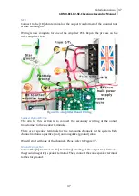
A ground level cable connects the [0V] terminal on the filament power
supply board to the star earth connection.
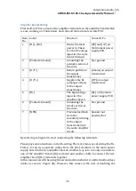
So, there will be 2 cables coming out from the [+V] and 3 from the (0V) terminals.
Each cable will be carrying around 750 milliamps of current.
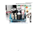
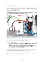
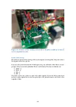
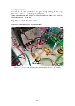
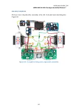
Figure 31 and Figure 32 show the wiring between the heater power supply board
and the heater filament terminals on the amplifier boards.
Summary of Contents for 6BM8/ECL82 SE
Page 1: ...Assembly Manual 6BM8 ECL82 SE 2 5W Classique MKII Version 3 0 Caledonian Audio ...
Page 6: ...6 ...
Page 10: ...10 Figure 2 Filament supply board with the four diodes ...
Page 16: ...16 Figure 8 Main power supply PCB fully populated ...


