


40
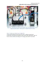
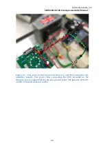
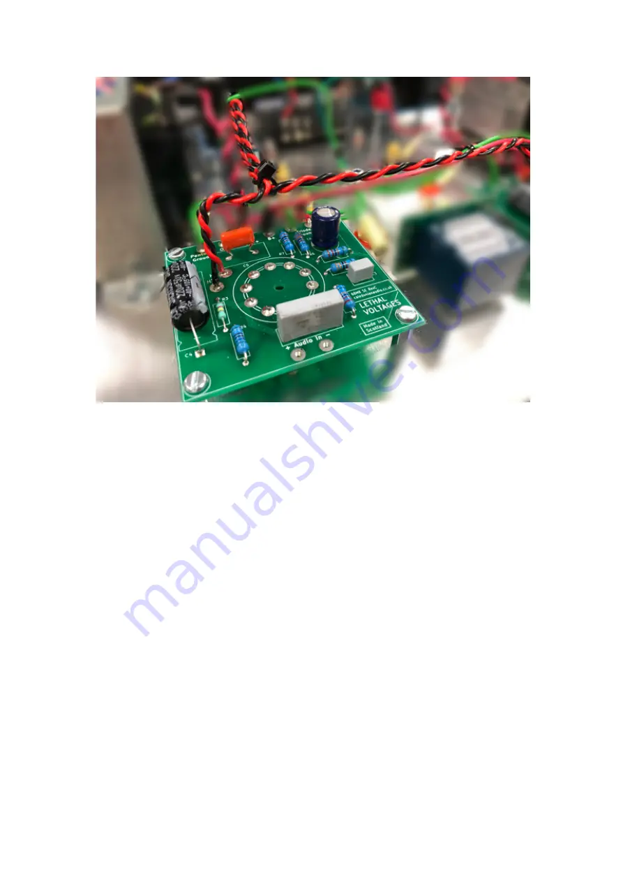
Figure 32 - Heater cables coming connected to the [H1] and [H2] terminals
on the amplifier boards.
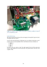
Audio cables wiring
We will now perform the wiring of the audio signals, starting from the point where
the signals enter the system.
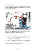
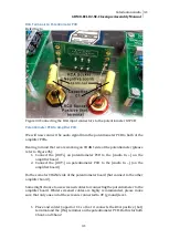
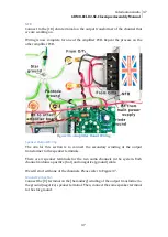
If you see the potentiometer IO PCB (Figure 33), you will notice that there are two
groups of four terminals (labelled Chan1 and Chan2). The four terminals are:
1.
[OUT +]
2.
[OUT –]
3.
[IN +]
4.
[IN –]
The idea is that we want to route the audio signals from the RCA connectors
(where audio signals first enter the system) to the potentiometer and then to the
amplifier PCBs.
Summary of Contents for 6BM8/ECL82 SE
Page 1: ...Assembly Manual 6BM8 ECL82 SE 2 5W Classique MKII Version 3 0 Caledonian Audio ...
Page 6: ...6 ...
Page 10: ...10 Figure 2 Filament supply board with the four diodes ...
Page 16: ...16 Figure 8 Main power supply PCB fully populated ...