ION EXTERNAL INTERFACES DESCRIPTION
- Ion Technical Information Manual
14
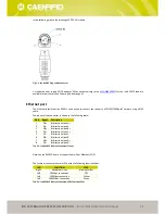
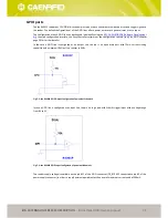
In the following table the pinout of the GPIO DB15 socket connector is shown. Connector external shell is connected to
GND.
Pin #
Signal
Description
1
GPIO0
General-purpose IO #0
2
GPIO2
General-purpose IO #2
3
GPIO4
General-purpose IO #4
4
GPIO6
General-purpose IO #6
5
GPIO8
General-purpose IO #8
6
GPIO10
General-purpose IO #10
7
GPIO12
General-purpose IO #12
8
GND
Ground
9
GPIO1
General-purpose IO #1
10
GPIO3
General-purpose IO #3
11
GPIO5
General-purpose IO #5
12
GPIO7
General-purpose IO #7
13
GPIO9
General-purpose IO #9
14
GPIO11
General-purpose IO #11
15
DC_BYPASS
Input supply voltage bypass (500mA max)
-
Shell
External shell (connected to Ground)
Tab. 3.4: Ion R4301P GPIO Connector Pinout
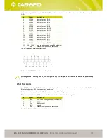
Fig. 3.5: Ion R4301P DB15 Socket Connector Pins Position
Warning: avoid connecting the DC_BYPASS signal to any of GPIO pins, otherwise the reader can be permanently
damaged.
USB host ports
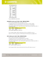
Ion R4301P reader has 2 USB 2.0 High Speed host ports that can be used to connect external devices like WI-FI or
Bluetooth adapters, GPS receivers or flash pen drives.
Each port is able to provide up to 500mA supply current at 5Vdc voltage.
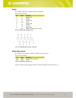
The connector is a 4 pins TYPE A receptacle. The pinout is described in the following table:
Pin #
Signal
Description
1
Vbus
+5V USB bus voltage output (500mA max)
2
D-
USB D- signal
3
D+
USB D+ signal
4
GND
Ground
-
Shell
External shell (connected to Ground)
Tab. 3.5: Ion R4301P USB Connectors Pinout


