


BEST
User’s Manual
BEST Local GUI
31
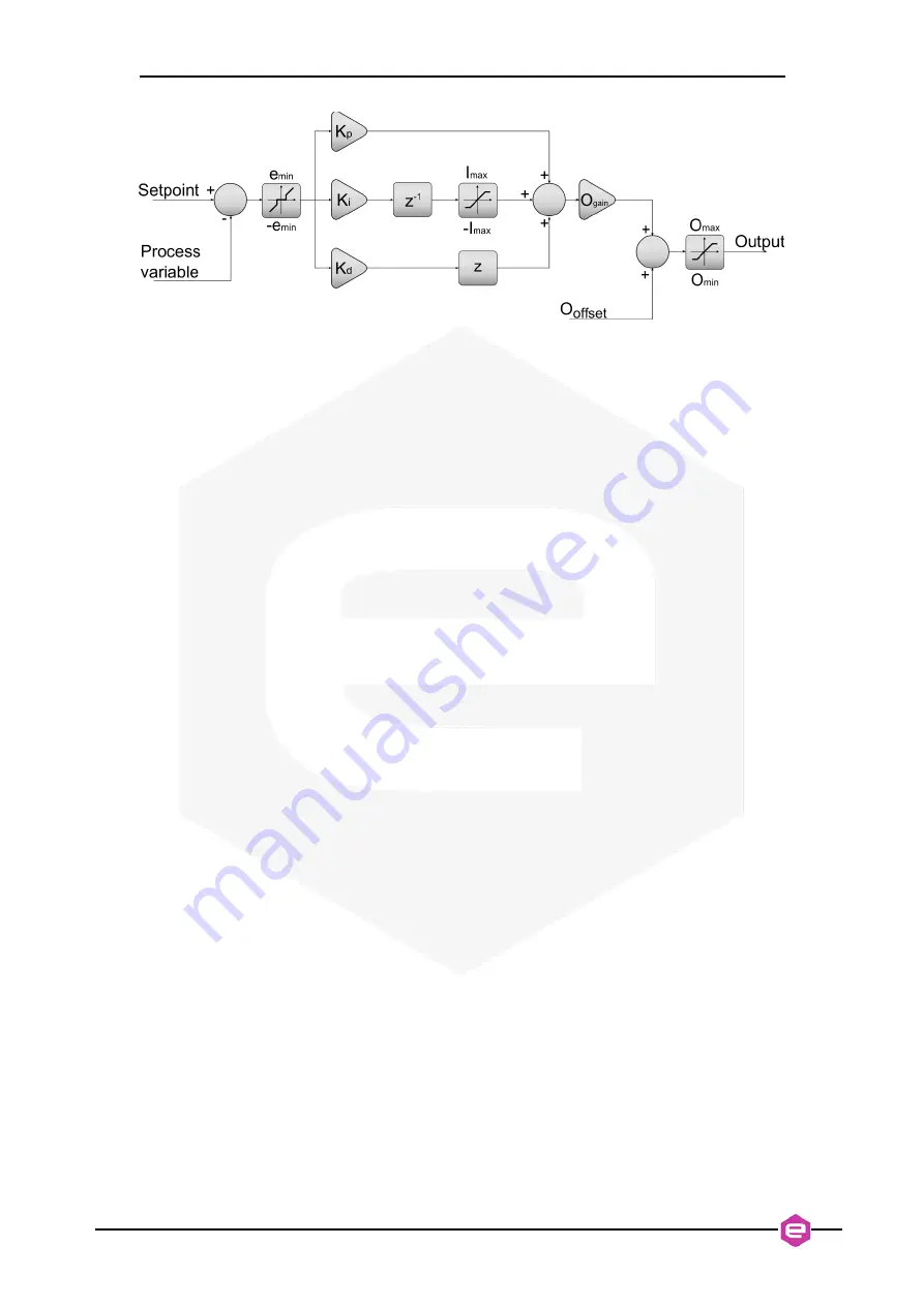
Figure 23
: PID Regulator architecture
The “e
min
” value set the smallest error value which is taken into account for the PID
calculation. All smaller values are trimmed to zero. In most cases this parameter
should be set at zero, although it can be used to stop the controller if a predefined
error from the loop target is reached and the user wants to freeze the system and avoid
continuous very small corrections. It sets the minimum tuning bandwidth of the
closed-loop feedback.
The “I
max
” parameter sets the saturation limit of the integral part of the PID controller.
The PID output (in Volts) is limited between the set “O
min
” and “O
max
” values. It is
recommended to set these values carefully in order to prevent any potential damage to
the input stage of piezoelectric actuator driver/amplifier or even to the actuator itself.
For example, piezoelectric actuators often have asymmetric input voltage ranges,
much wider in a given polarity than in the opposite. N.B.: we point out that it is
possible to set further limits for the minimum and maximum value of the
PreDAC
output, which are set in a lower level firmware and therefore provide an additional
protection layer. Please refer to the
PreDAC
User's Manual, “MIN” and “MAX”
Commands.
The output of the PID controller is multiplied by the “O
gain
” value to change the gain
of the closed loop and, mainly, to invert the PID response. Normally this parameter is
only set either to 1 or -1.
“O
offset
” can be used to steer the beam to a selected working point. Furthermore, In
order to benefit from the maximum excursion in both direction of the piezoelectric
actuator, it is suggested to set O
offset
at the center of the piezo driver/amplifier input
range.
By pressing the “Update” button, all new parameters are downloaded to the controller
on the FPGA and they take effect immediately.